1. Introduction
Thank you for choosing the Naweisz 30V 10A Adjustable DC Power Supply. This device is designed for precise and stable power output, suitable for a wide range of applications including laboratory experiments, electronic production, LED testing, and DIY projects. This manual provides essential information for the safe and efficient operation of your power supply.
2. Safety Instructions
Please read and understand all safety instructions before operating the device. Failure to follow these instructions may result in electric shock, fire, or damage to the product.
- Ensure the power supply is connected to a grounded outlet with the correct voltage (110V ± 10%, 60Hz for US models).
- Do not operate the device in wet or damp conditions. Keep it away from liquids.
- Do not open the casing of the power supply. There are no user-serviceable parts inside. Refer all servicing to qualified personnel.
- Avoid blocking the ventilation openings. Proper airflow is essential for cooling.
- Always disconnect the power cord before cleaning or moving the unit.
- Ensure the output is OFF before connecting or disconnecting loads to prevent damage to the power supply or the connected device.
- Do not exceed the maximum output voltage (30V) or current (10A) ratings.
3. Product Overview

Figure 3.0: Naweisz 30V 10A Adjustable DC Power Supply. This image shows the overall appearance of the power supply unit from an angled front view, highlighting its compact design and digital display.
3.1 Front Panel
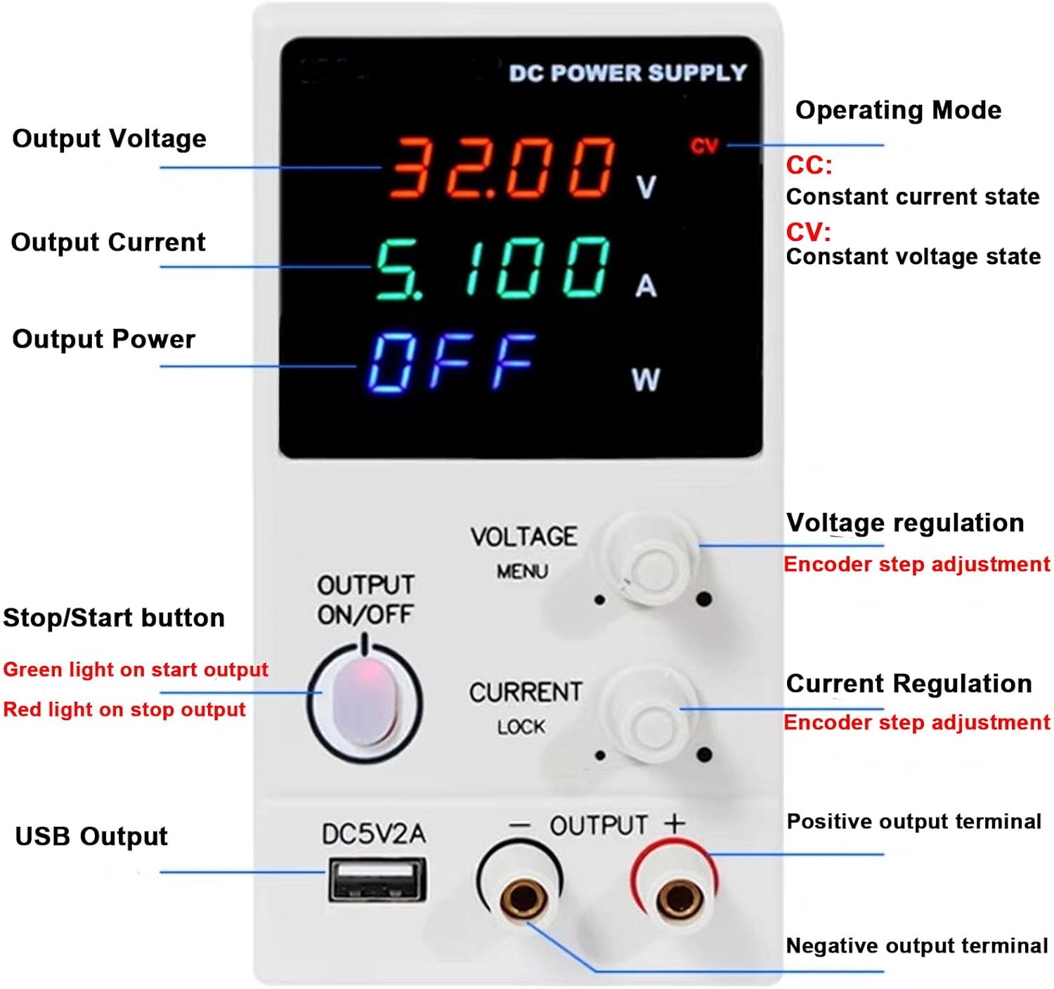
Figure 3.1: Front Panel Layout of the Naweisz DC Power Supply. This image shows the digital LED display for voltage, current, and power, along with the rotary encoder knobs for voltage and current regulation, the output ON/OFF button, USB output, and positive/negative output terminals.
- Digital LED Display: Shows real-time voltage (V), current (A), and power (W) readings. Also indicates operating mode (CV/CC).
- Voltage Regulation Knob: Rotary encoder for precise adjustment of output voltage. Press to switch between coarse and fine adjustment.
- Current Regulation Knob: Rotary encoder for precise adjustment of output current. Press to switch between coarse and fine adjustment.
- Output ON/OFF Button: Toggles the power output. Green light indicates output is ON, red light indicates output is OFF.
- USB Output (DC5V2A): Provides a fixed 5V, 2A USB power output for charging or powering compatible devices.
- Output Terminals (+/-): Connect your load here. Red for positive, black for negative.
3.2 Rear Panel

Figure 3.2: Rear Panel Layout. This image displays the main power switch, cooling fan, AC input socket, and fuse box location.
- Power Switch: Main power switch for the unit.
- Cooling Fan: Automatically activates to dissipate heat during operation. Ensure it is not obstructed.
- AC Input: Socket for connecting the AC power cord.
- Fuse Box: Contains the protective fuse.
4. Setup
- Unpacking: Carefully remove the power supply from its packaging. Verify all components listed in the package contents are present (power supply unit, power cord, alligator clip leads, user manual).
- Placement: Place the power supply on a stable, flat surface with adequate ventilation. Ensure there is sufficient space around the unit for airflow, especially around the cooling fan at the rear.
- Power Connection:
- Ensure the power switch on the rear panel is in the OFF position.
- Connect the provided AC power cord to the AC Input socket on the rear panel.
- Plug the other end of the power cord into a grounded 110V AC, 60Hz power outlet.
- Initial Power On: Flip the power switch on the rear panel to the ON position. The digital display on the front panel should illuminate.
5. Operating Instructions
5.1 Setting Voltage and Current
- Ensure Output is OFF: Before connecting any load, ensure the Output ON/OFF button is in the OFF (red light) state.
- Preset Voltage:
- Rotate the Voltage Regulation knob to adjust the desired voltage.
- Press the Voltage Regulation knob to switch between coarse adjustment (larger steps) and fine adjustment (0.01V steps). The display will show the preset voltage.
- Preset Current:
- Rotate the Current Regulation knob to adjust the desired current limit.
- Press the Current Regulation knob to switch between coarse adjustment (larger steps) and fine adjustment (0.001A steps). The display will show the preset current.
- Note: It is recommended to set the current limit slightly above the expected operating current of your load to prevent accidental current limiting.
5.2 Connecting Load and Output Control
- Connect Load: Connect your device or circuit to the output terminals. Ensure correct polarity: positive (+) to red terminal, negative (-) to black terminal. Use the provided alligator clip leads if suitable.
- Activate Output: Press the Output ON/OFF button. The light will turn green, indicating that power is now being supplied to your load. The display will show the actual output voltage, current, and power.
- Constant Voltage (CV) and Constant Current (CC) Modes:
- The power supply automatically switches between CV and CC modes depending on the load.
- When operating in Constant Voltage (CV) mode, the output voltage remains stable at the preset value, and the current varies according to the load. The "CV" indicator on the display will be lit.
- When operating in Constant Current (CC) mode, the output current remains stable at the preset limit, and the voltage varies according to the load. This occurs if the load resistance is too low for the preset voltage, causing the current to reach its limit. The "CC" indicator on the display will be lit.
- Deactivate Output: To stop power delivery, press the Output ON/OFF button again. The light will turn red, and the output will be disconnected. This allows you to safely adjust settings or disconnect the load without powering down the entire unit.
5.3 Using the USB Output
The dedicated DC5V2A USB interface provides a stable 5V, 2A output. Simply connect your USB-powered device to this port. This output is independent of the main adjustable DC output.
6. Maintenance
- Cleaning: Disconnect the power supply from the AC outlet before cleaning. Use a soft, dry cloth to wipe the exterior. Do not use abrasive cleaners or solvents.
- Ventilation: Regularly check that the cooling fan and ventilation openings are free from dust and debris. Use compressed air to clear any blockages if necessary.
- Fuse Replacement: If the unit does not power on, the fuse may need replacement.
- Disconnect the power cord from the AC outlet.
- Locate the fuse box on the rear panel (refer to Figure 3.2).
- Carefully open the fuse box and replace the blown fuse with a new one of the same type and rating.
- Close the fuse box securely.
- Storage: When not in use for extended periods, store the power supply in a cool, dry place, away from direct sunlight and extreme temperatures.
7. Troubleshooting
| Problem | Possible Cause | Solution |
|---|---|---|
| Unit does not power on. | No AC power; Blown fuse; Power switch off. | Check AC power cord connection and outlet. Replace fuse if blown. Ensure rear power switch is ON. |
| No output voltage/current when Output is ON. | Output ON/OFF button is OFF; Load not connected correctly; Output current limit set too low. | Press Output ON/OFF button (green light). Check load connections and polarity. Increase current limit. |
| Output voltage is lower than set value. | Operating in Constant Current (CC) mode; Load resistance too low. | Check if CC indicator is lit. Increase current limit or reduce load resistance if appropriate. |
| Unit overheats. | Blocked ventilation; Excessive load. | Ensure cooling fan and vents are clear. Reduce load or operating time. |
| Display shows "OVP", "OCP", or "OPP". | Overvoltage, Overcurrent, or Overpower Protection activated. | Disconnect load, check for short circuits or excessive power draw. Adjust settings within safe limits. |
8. Specifications
| Feature | Specification |
|---|---|
| Model | NP3010HC |
| Output Voltage | 0-30V (Max) |
| Output Current | 0-10A (Max) |
| Output Power | Max 300W |
| Display | 4-digit three-color LED display (V/A/W) |
| Resolution | 0.01V / 0.001A |
| Protection | Overvoltage Protection (OVP), Overcurrent Protection (OCP), Overpower Protection (OPP) |
| USB Output | DC 5V, 2A |
| Input Voltage | 110V ± 10%, 60Hz (US Standard) |
| Dimensions (L x W x H) | 11.42 x 3.94 x 6.69 inches (290 x 100 x 170 mm) |
| Item Weight | 3.52 pounds (1.6 Kilograms) |
| Operating Temperature | 0°C to +40°C |
| Relative Humidity | ≤ 90% |

Figure 8.1: Product Dimensions. The image shows the compact design with measurements: 235mm (length), 80mm (width), and 155mm (height).
9. Warranty and Support
Naweisz provides comprehensive support for its products:
- Warranty: This product comes with a 24-month warranty from the date of purchase.
- Returns: Enjoy 45-day free returns.
- Technical Support: Lifetime technical support is available. For any issues or inquiries regarding the use of your unit, please contact Naweisz customer service via email.
For further assistance, please refer to the contact information provided with your purchase or visit the official Naweisz store online.
