
1. Introduction
This manual provides detailed instructions for the installation, operation, and maintenance of the Aoleaby JK Smart BMS B1A8S10P. This Battery Management System is designed for 4S to 8S Li-ion, LiFePO4, and LTO battery packs, offering active balancing and comprehensive protection features. Please read this manual thoroughly before installation and use to ensure safe and efficient operation.
2. Key Features
- Active Balance: 1A active balancing current to equalize cell voltages, improving battery efficiency and lifespan.
- Bluetooth (BT) Communication: Connect via the JK Smart APP for real-time monitoring and configuration of BMS parameters.
- RS485 Communication: For advanced system integration and data communication.
- Comprehensive Protection: Includes protection against over-charge, over-discharge, over-current, short circuit, and low-temperature charging cutoff.
- Heat Dissipation: Double aluminum sheet design with four-sides breathable structure for efficient heat management.
- Customizable Functions: Supports optional features like CANBUS, heating function, and LCD display (may require customization).

Figure 1: Overview of the JK Smart BMS B1A8S10P, highlighting its main features such as BT/RS485 function, 1A balance current, support for 4S-8S battery strings, 100A charge/discharge current, dimensions (153*186*18mm), and compatibility with Li-ion, LiFePO4, and LTO battery types. For more information, scan the QR code: http://qr17.cn/BApbC0

Figure 2: Detailed view of the JK Smart BMS B1A8S10P ports, including connections for temperature sensor, RS485 (by default), LCD (by default), and heat function (customization needed). Other functions may be customized.

Figure 3: Illustration of the BMS's double aluminum sheet and four-sides breathable design, engineered for efficient heat dissipation to maintain optimal operating temperature.

Figure 4: The BMS offers an integrated solution with 10 types of protection, including short circuit, moisture, overcharge, over-discharge, temperature, balanced, electrostatic, dust, overcurrent, and drop protection. For more information, scan the QR code: http://qr17.cn/BApbC0
3. Specifications
The following table details the technical specifications for the JK-B1A8S10P model:
| Parameter | Specification (JK-B1A8S10P) |
|---|---|
| Li-ion Strings | 3s~8s |
| Lifepo4 Strings | 4s~8s |
| LTO Strings | 6s~8s |
| Balance mode | Active Equalization/Balance |
| Active Balanced Current | 1A |
| Main Circuit Conduction Internal | 0.3mΩ |
| Continuous output current | 100A |
| Maximum output current | 200A |
| Over Charge Protection Current (adjustable) | 10-100A |
| Other interfaces (customizable) | RS485/CAN/Display interface |
| Wiring Output | Common port |
| Single Cell Voltage | 1-5V |
| Voltage Acquisition | ±5mV |
| Over Charge Protection Voltage | 1.2-4.35V Adjustable |
| Over Charge Release Voltage | 1.2-4.35V Adjustable |
| Over Current Detect Delay | 2-120S Adjustable |
| Over Discharge Protection Voltage | 1.2-4.35V Adjustable |
| Over Discharge Release Voltage | 1.2-4.35V Adjustable |
| Quantity of Temperature Detection | 3 pcs |
| Temperature Protection | Yes |
| Short Circuit Protection | Yes |
| Coulomb Counter | Yes |
| Bluetooth Function | APP For Android/IOS Available |
| GPS (Optional) | Contact customer service support |
| Size | 153*136*18mm |

Figure 5: A comprehensive table outlining the technical specifications for the JK-B1A8S10P model, including supported battery types, balance current, protection parameters, and physical dimensions.
4. Installation and Wiring
Proper installation and wiring are crucial for the safe and correct operation of the BMS. Incorrect wiring can damage the BMS, battery pack, or connected equipment. Always ensure the battery pack is disconnected from any loads or chargers before beginning installation.
4.1 Safety Precautions
- Always wear appropriate personal protective equipment (PPE), including safety glasses and insulated gloves.
- Ensure all power sources are disconnected before handling battery terminals or BMS connections.
- Avoid short-circuiting battery terminals or BMS connections.
- Verify correct polarity for all connections.
- Work in a well-ventilated area.
4.2 Wiring Diagram
Refer to the wiring diagram below for connecting the BMS to your battery pack, load, and charger. The BMS uses a common port for charge and discharge.
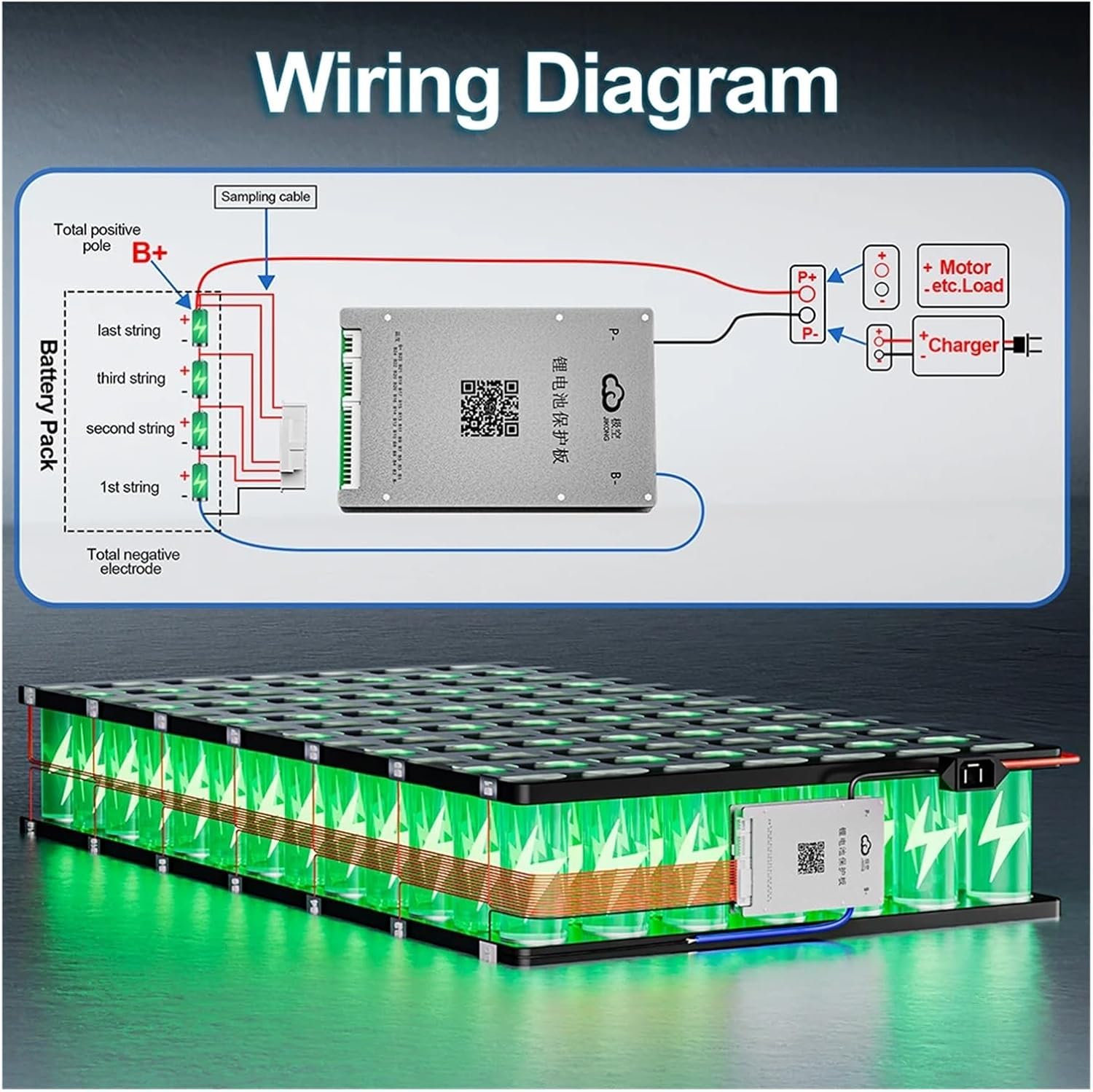
Figure 6: Wiring diagram illustrating the connection of the JK Smart BMS to a battery pack (4S shown as an example), a motor/load, and a charger. The 'B-' terminal connects to the total negative of the battery pack, and 'P-' connects to the negative of both the load and charger. The 'B+' terminal connects to the total positive of the battery pack. Sampling cables are connected to each cell string. For more information, scan the QR code: http://qr17.cn/BApbC0
4.3 Connection Steps
- Connect B- to Battery Pack Negative: Connect the main negative terminal (B-) of the BMS to the total negative terminal of your battery pack.
- Connect B+ to Battery Pack Positive: Connect the main positive terminal (B+) of the BMS to the total positive terminal of your battery pack.
- Connect Sampling Cables: Carefully connect the individual cell voltage sampling cables from the BMS to each cell string of your battery pack, starting from the lowest voltage cell (B0) up to the highest (B8 for an 8S system). Ensure the order and polarity are correct.
- Connect P- to Load/Charger Negative: Connect the negative terminal (P-) of the BMS to the negative terminals of both your load (e.g., motor) and your charger.
- Connect Load/Charger Positive: Connect the positive terminals of your load and charger directly to the total positive terminal of your battery pack (B+).
- Connect Temperature Sensors: If using, connect the temperature sensors to the designated ports on the BMS and place them strategically on the battery cells for accurate temperature monitoring.
- Connect Communication Interfaces: If using RS485 or other customizable interfaces, connect them according to your system requirements.
Important: Always double-check all connections before applying power. Incorrect wiring can lead to severe damage or fire.
5. Operation
5.1 Initial Power-Up
After completing all wiring and verifying connections, apply power to the battery pack. The BMS should power on automatically. Observe any indicator lights or listen for audible cues.
5.2 Using the JK Smart APP (Bluetooth)
The JK Smart BMS features Bluetooth connectivity, allowing you to monitor and configure your battery system via a dedicated mobile application.
- Download the APP: Search for "JK Smart BMS" or similar in your mobile device's app store (Android/iOS).
- Connect via Bluetooth: Enable Bluetooth on your mobile device. Open the JK Smart APP and search for available BMS devices. Select your BMS from the list to connect.
- Monitoring: The APP will display real-time battery parameters such as total voltage, individual cell voltages, charge/discharge current, temperature, state of charge (SOC), and active balance status.
- Configuration: Access settings within the APP to adjust various protection parameters (e.g., over-charge/discharge voltage, over-current limits, temperature thresholds) as needed for your specific battery chemistry and application. Refer to the APP's internal help or the manufacturer's website for detailed parameter explanations.
5.3 RS485 Communication
For integration into larger systems or advanced monitoring, the BMS supports RS485 communication. Refer to the manufacturer's communication protocol documentation for details on integrating with external controllers or displays.
6. Maintenance
The JK Smart BMS is designed for low maintenance. However, periodic checks can help ensure its longevity and optimal performance.
- Visual Inspection: Periodically inspect the BMS and all wiring for any signs of damage, corrosion, or loose connections.
- Firmware Updates: Check the manufacturer's website or the JK Smart APP for any available firmware updates. Follow instructions carefully if updating.
- Cleanliness: Keep the BMS free from dust and moisture. Use a dry, soft cloth for cleaning.
- Temperature: Ensure the BMS operates within its specified temperature range. Good ventilation around the battery pack and BMS is important.
7. Troubleshooting
If you encounter issues with your JK Smart BMS, refer to the following common troubleshooting steps:
7.1 BMS Not Powering On
- Check Main Connections: Verify that the B- and B+ connections to the battery pack are secure and have correct polarity.
- Check Cell Voltage: Ensure that the battery pack has sufficient voltage to power the BMS.
- Check Sampling Wires: Confirm that all cell sampling wires are correctly connected and not damaged.
7.2 Cell Imbalance Issues
- Verify Balance Current: Ensure the active balance function is enabled in the APP and operating.
- Check Cell Health: Individual cells with significantly different internal resistance or capacity may struggle to balance effectively. Consider checking individual cell health.
- Operating Time: Active balancing takes time. Allow the BMS sufficient time to balance cells, especially after initial setup or deep discharge.
7.3 Over-Protection Triggered
- Over-Charge/Discharge: Check battery voltage. If it's outside safe limits, the BMS will protect. Adjust charging/discharging habits or check charger/load.
- Over-Current: Reduce load or charging current. Ensure your application's current draw is within the BMS's continuous and peak current ratings.
- Temperature Protection: Check battery and BMS temperature. Improve ventilation or reduce load if overheating.
- Short Circuit: Immediately disconnect all power. Inspect wiring for any short circuits and repair before reconnecting.
7.4 Bluetooth Connection Issues
- Enable Bluetooth: Ensure Bluetooth is enabled on your mobile device.
- App Permissions: Grant necessary permissions to the JK Smart APP.
- Proximity: Ensure your device is within Bluetooth range of the BMS.
- Restart: Try restarting the APP or your mobile device.
If problems persist after troubleshooting, contact customer support for assistance.
8. Warranty and Support
For warranty information, please refer to the product documentation provided at the time of purchase or contact your retailer. For technical support, inquiries regarding customizable features (such as GPS), or advanced troubleshooting, please contact Aoleaby customer service.
Manufacturer: Aoleaby
Model: JK Smart BMS B1A8S10P
ASIN: B0D2T83BGK