1. Introduction
This manual provides detailed instructions for the installation, operation, and maintenance of your Geloo Universal Motorcycle Digital Tachometer Speedometer. Please read this manual thoroughly before installation and use to ensure proper function and safety.

Figure 1.1: Geloo Digital Tachometer in use. This image shows the digital tachometer installed on a motorcycle, providing a rider's perspective of the display while on the road.
2. Product Overview
The Geloo Universal Motorcycle Digital Tachometer Speedometer is a multi-functional instrument designed for motorcycles. It integrates a tachometer, speedometer, and gear indicator into a single unit, providing essential riding information. Key features include:
- Integrated tachometer, speedometer, and gear indicator.
- High-precision speed sensor included.
- Durable ABS shell with clear lens, waterproof and shock-resistant.
- Anti-glare LCD display with adjustable 7-color backlight for clear visibility in all lighting conditions.
- Applicable to 1, 2, and 4-cylinder motorcycle models.

Figure 2.1: Geloo Universal Motorcycle Digital Tachometer Speedometer. This image shows the main unit of the digital tachometer and speedometer, highlighting its compact design and clear display.
2.1. Display Components

Figure 2.2: Labeled diagram of the display components. This diagram points out various indicators on the meter, including left turn signal, high beam display, N gear display lamp, oil signal, water temperature, right turn signal, speed, clock, speed pulse number, tachometer (digital display), fuel indicator, battery under voltage lamp, and engine fault light.
3. Specifications
| Material | ABS Plastic |
| Dimensions | 140 x 99 mm (5.5 x 3.9 inches) |
| Supply Voltage | DC 12V |
| Operating Voltage | 9-16V |
| Speed Display Range | 0 ~ 299 km/h |
| Odometer Display Range | 0 ~ 99999.9 km (miles) |
| Trip Meter | Max 999.9 km |
| Gear Position Display | 1 to 6 |
| Operating Temperature | -30 to 85 °C |
| LCD Backlight Color | 7 adjustable colors (default blue) |
| Model Number | GJ001 |
4. Setup and Installation
Proper installation is crucial for the accurate operation of the digital tachometer. It is recommended that installation be performed by a qualified technician if you are unfamiliar with motorcycle electrical systems.
4.1. Mounting the Unit
Securely mount the tachometer unit to your motorcycle's handlebar or dashboard using the provided bracket. Ensure the unit is positioned for clear visibility while riding and does not obstruct your view or controls.

Figure 4.1: Tachometer mounted on a motorcycle. This image illustrates the digital tachometer installed on a motorcycle's handlebar, showing its integration into the rider's view.
4.2. Wiring Diagram and Connections
The unit comes with a wiring harness. Refer to the diagram below for correct connections. Incorrect wiring can damage the unit or the motorcycle's electrical system.

Figure 4.2: Wiring Diagram. This diagram details the color-coded wires and their corresponding functions for connecting the tachometer to the motorcycle's electrical system. Key connections include power, ground, speed signal, RPM signal, gear position signals, turn signals, high beam, oil signal, water temperature, fuel indicator, battery under voltage lamp, and engine fault light.
- Pink: 1st Gear
- Blue-Red: 2nd Gear
- Green-Black: 3rd Gear
- Yellow-Red: 4th Gear
- Brown-White: 5th Gear
- Red-White: 6th Gear
- Green-Red: Neutral Gear
- Brown-Red: Engine Failure
- Orange: Turn Left Signal
- Black: Positive Power
- Green-Blue: Water Temperature
- Yellow-White: Oil Level
- Purple: Battery
- Light-Blue: Right Turn Signal
- Black-Yellow: RPM Signal
- Green: Negative (Ground)
- Blue: High Beam
- Red: Speed Signal
- Yellow: Speed Positive
4.3. Speed Sensor Installation
The speed sensor is essential for accurate speed readings. Install the sensor in a location where it can detect wheel rotation, typically near the front or rear wheel. Ensure the sensor is securely fastened and properly aligned.

Figure 4.3: Tachometer unit with included speed sensor. This image displays the main unit alongside its speed sensor and mounting bracket, illustrating the complete package for installation.
5. Operating Instructions
5.1. Power On/Off
The unit powers on automatically with the motorcycle's ignition and powers off when the ignition is turned off.
5.2. Display Modes
The display shows current speed, RPM, gear position, odometer (ODO), and trip meter (TRIP). Use the buttons on the unit to cycle through different display modes or settings.
5.3. Adjusting Backlight Color
The LCD backlight offers 7 adjustable colors. To change the backlight color, press and hold the right button while the unit is in ODO mode. Cycle through the colors by pressing the button briefly until your desired color is displayed.
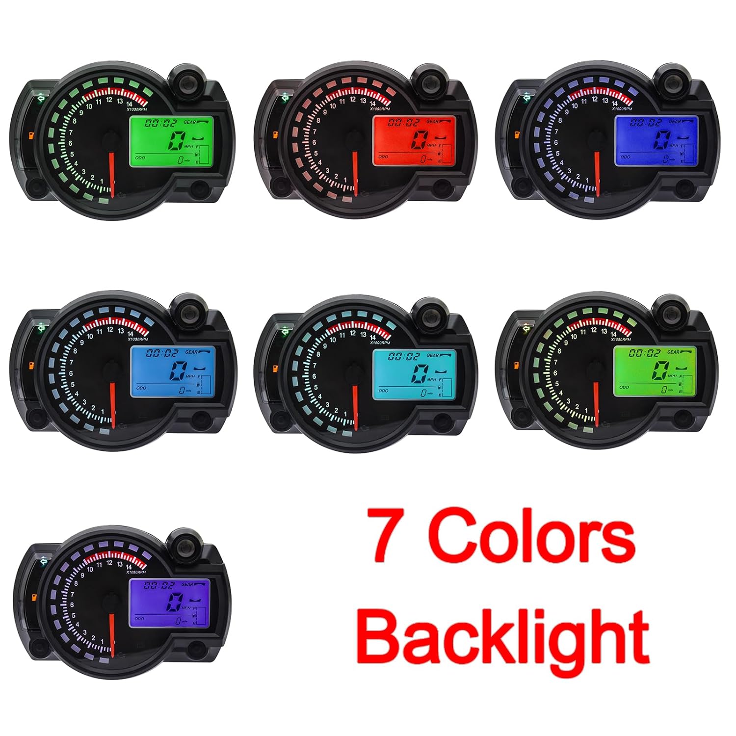
Figure 5.1: Examples of the 7 adjustable backlight colors. This image showcases the tachometer display in various backlight colors, demonstrating the customization option for improved visibility and aesthetics.
5.4. Setting Time and Units
Specific instructions for setting the clock and switching between km/h and mph or km and miles are typically found in the detailed manual provided with the product. Generally, these settings are accessed by pressing and holding specific buttons in certain display modes (e.g., ODO or TRIP) to enter a setup menu.
6. Maintenance
- Cleaning: Use a soft, damp cloth to clean the display and casing. Avoid abrasive cleaners or solvents that could damage the plastic.
- Inspection: Periodically check all wiring connections to ensure they are secure and free from corrosion. Inspect the speed sensor for any damage or misalignment.
- Water Resistance: The unit is designed to be waterproof and shock-resistant. However, avoid prolonged submersion or high-pressure water jets directly on the unit.
7. Troubleshooting
- No Power: Check the power connections (Black wire for positive, Green wire for negative/ground) and ensure the motorcycle's ignition is on. Verify the battery voltage.
- Inaccurate Speed/RPM: Ensure the speed sensor is correctly installed and aligned. Check the RPM signal wire connection (Black-Yellow). For cylinder settings, refer to the specific instructions provided with the product for calibration.
- Display Issues (e.g., no backlight, flickering): Check all wiring connections. If the backlight is not working, try adjusting the color as per section 5.3.
- Moisture Inside Display: While designed to be waterproof, extreme temperature changes or prolonged exposure to high humidity can sometimes cause condensation. If this occurs, ensure all seals are intact and allow the unit to dry in a warm, dry environment. If the issue persists, contact support.
8. Warranty and Support
Information regarding product warranty and customer support is typically provided with the product packaging or on the manufacturer's official website. Please refer to those resources for details on warranty coverage, returns, and technical assistance.