1. Introduction
The Irfora FY128C Smart Digital Multimeter is a compact and intelligent electrical testing instrument designed for professionals, factories, schools, and home users. It is engineered to meet the safety requirements of the International Electrotechnical Safety Standard (IEC-61010) for electronic measuring instruments and handheld digital multimeters. This device offers accurate measurements for AC/DC voltage, resistance, frequency, continuity, live wire checking, and Non-Contact Voltage (NCV) detection.
Safety Precautions:
- Always ensure the multimeter is in good working condition before use.
- Do not attempt to measure voltages or currents exceeding the specified maximum limits.
- Exercise extreme caution when working with live circuits.
- Replace batteries promptly when the low battery indicator appears.
- Do not operate the multimeter if the casing is damaged or open.
2. Package Contents
Please check the package for the following items:
- 1 x Digital Multimeter (FY128C)
- 1 x Pair of Test Leads (Red and Black)
- 1 x User Manual (English)
3. Product Overview
The FY128C Smart Digital Multimeter features a large, backlit LCD display for clear readings, a built-in flashlight for dark environments, and a support bracket for convenient hands-free operation. Below is an illustration of the instrument's key components and functions.

Figure 3.1: Instrument Functions Overview

Figure 3.2: Large LCD Display for Easy Reading
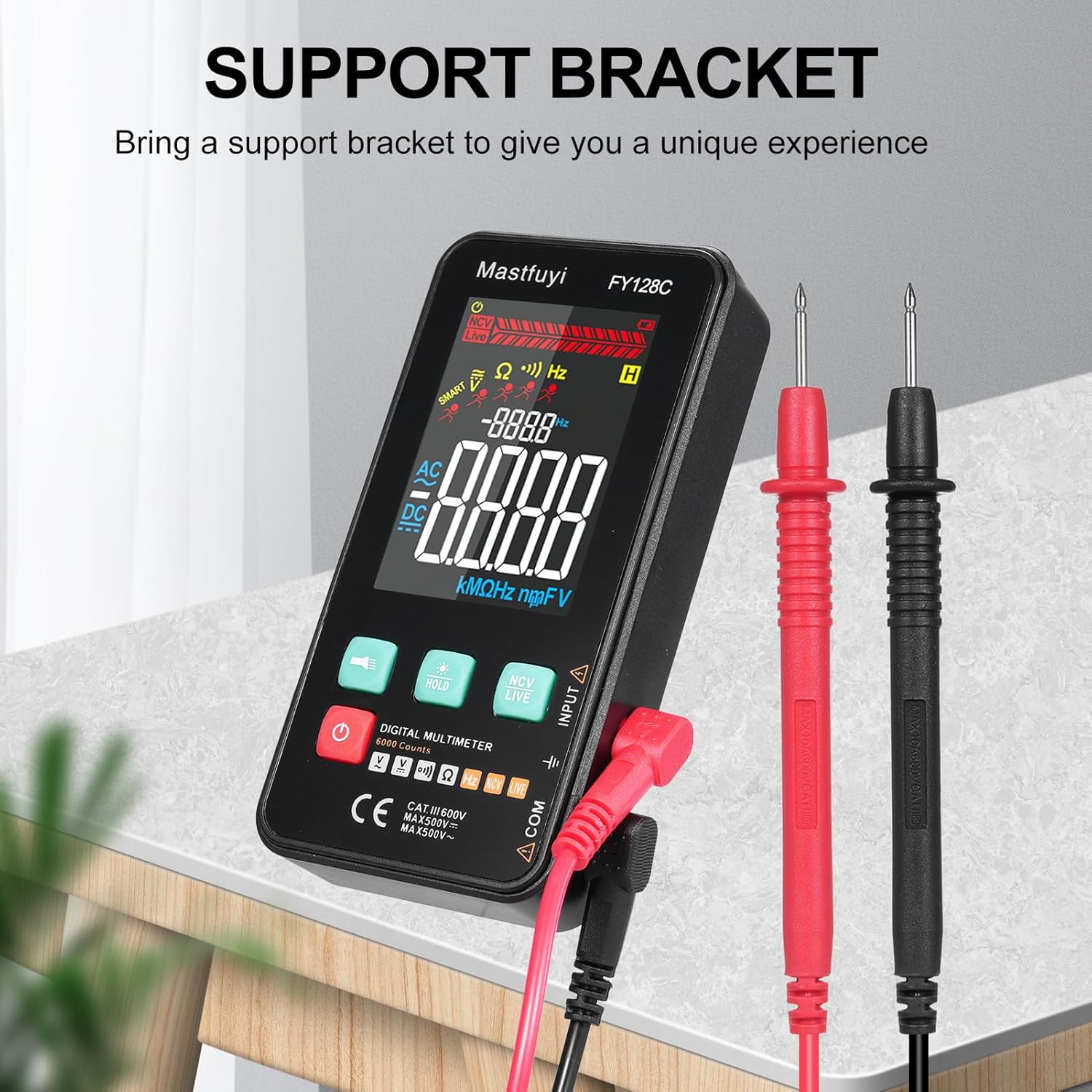
Figure 3.3: Multimeter with Support Bracket and Test Leads
4. Setup
4.1 Battery Installation
- Ensure the multimeter is powered off.
- Locate the battery compartment cover on the back of the device.
- Use a screwdriver to open the battery compartment.
- Insert two 1.5V AAA batteries, observing the correct polarity (+/-).
- Replace the battery compartment cover and secure it with the screw.
4.2 Connecting Test Leads
- Insert the black test lead into the 'COM' (Common) input jack.
- Insert the red test lead into the 'INPUT' jack for most measurements (voltage, resistance, frequency, continuity).
- Ensure the test leads are securely connected before taking any measurements.
5. Operating Instructions
The FY128C Multimeter offers two primary measurement modes: Auto Identification and Manual Switching.
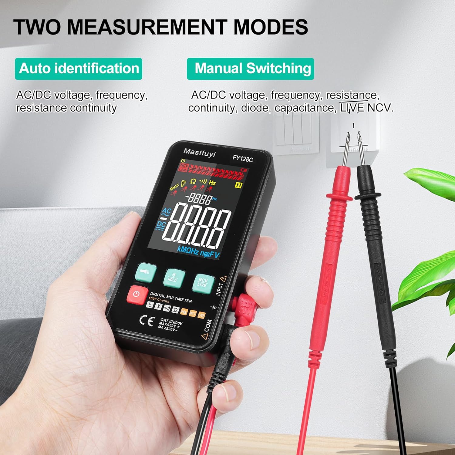
Figure 5.1: Two Measurement Modes
5.1 Power On/Off
Press the power button (U) to turn the multimeter on or off. The device features an auto-shutdown function to conserve battery power after a period of inactivity.
5.2 Auto Identification Mode
In this mode, the multimeter automatically identifies and measures AC/DC voltage, frequency, resistance, and continuity. Simply connect the test leads to the circuit or component, and the device will display the appropriate measurement.
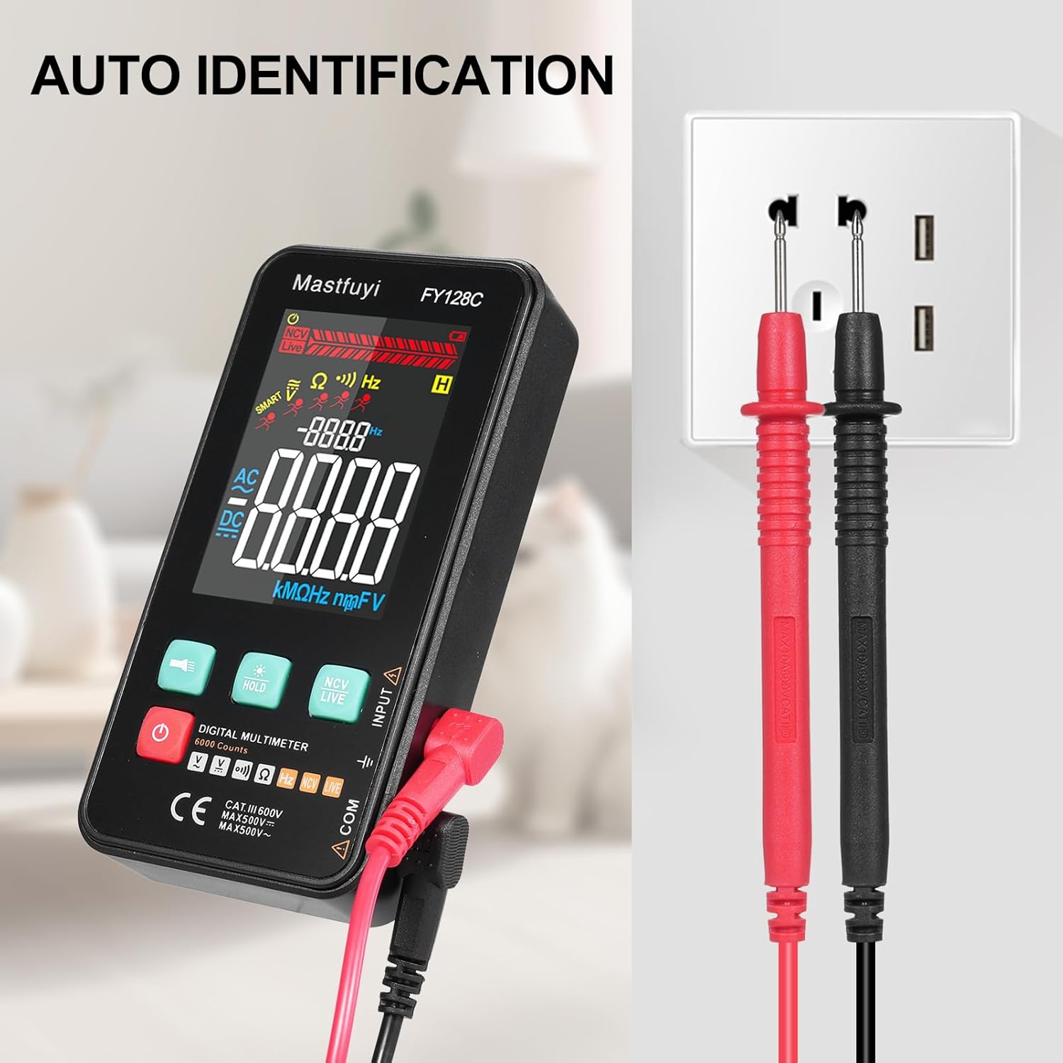
Figure 5.2: Auto Identification in Use
5.3 Manual Switching Mode
For specific measurements or when auto-identification is not desired, you can manually switch between functions. Press the 'MODE' button (often indicated by a symbol like a wave or function icon) to cycle through AC/DC voltage, frequency, resistance, continuity, and NCV/LIVE functions.
5.4 AC/DC Voltage Measurement
- Select the appropriate voltage mode (AC V or DC V) if in manual mode, or rely on auto-identification.
- Connect the test leads in parallel to the circuit or component you wish to measure.
- Read the voltage value on the LCD display.
5.5 Resistance Measurement
- Ensure the circuit or component is de-energized before measuring resistance.
- Select the resistance mode (Ω) if in manual mode.
- Connect the test leads across the component.
- Read the resistance value on the LCD display.
5.6 Frequency Measurement
- Select the frequency mode (Hz) if in manual mode.
- Connect the test leads to the circuit where you want to measure frequency.
- Read the frequency value on the LCD display.
5.7 Continuity Test
- Ensure the circuit or component is de-energized.
- Select the continuity mode (often indicated by a buzzer icon).
- Connect the test leads across the component or wire.
- If there is continuity (a complete circuit), the multimeter will emit an audible beep.
5.8 Live Wire Checking
This function helps identify live wires without direct contact.
- Select the 'LIVE' mode (often shared with NCV).
- Bring the red test lead probe close to the wire or outlet.
- The multimeter will indicate the presence of a live wire through visual (LED) and/or audible signals.

Figure 5.3: Live Wire Checking in Progress
5.9 NCV (Non-Contact Voltage) Test
The NCV function allows for safe detection of AC voltage without physical contact with the conductor.
- Select the 'NCV' mode.
- Bring the top part of the multimeter (NCV sensor area) close to the suspected voltage source.
- The device will indicate the presence of AC voltage with an audible beep and/or visual indicator (e.g., LED lights). The intensity of the signal may vary with voltage strength and proximity.

Figure 5.4: NCV Insulation Safety Test
5.10 Data Hold Function
Press the 'HOLD' button to freeze the current reading on the display. Press it again to release the hold and resume live measurements.
5.11 Flashlight and Backlight
Press the flashlight button (often indicated by a light bulb icon) to turn on the built-in flashlight. The LCD display also has a backlight for improved visibility in low-light conditions, which typically activates automatically or can be toggled with a dedicated button.
6. Maintenance
6.1 Cleaning
Wipe the multimeter casing with a damp cloth and mild detergent. Do not use abrasive cleaners or solvents. Ensure the device is completely dry before use.
6.2 Battery Replacement
When the low battery indicator appears on the display, replace the batteries as described in Section 4.1. Always use fresh 1.5V AAA batteries.
6.3 Storage
If the multimeter will not be used for an extended period, remove the batteries to prevent leakage. Store the device in a cool, dry place, away from direct sunlight and extreme temperatures.
7. Troubleshooting
This section addresses common issues you might encounter with your FY128C Smart Digital Multimeter.
| Problem | Possible Cause | Solution |
|---|---|---|
| No display or dim display | Low batteries; Device not powered on; Damaged display. | Replace batteries; Press power button; Contact support if display is damaged. |
| Inaccurate readings | Incorrect mode selected; Poor test lead connection; External interference. | Verify mode selection; Ensure leads are firmly connected; Move away from strong electromagnetic fields. |
| Continuity test not beeping | Open circuit; Continuity mode not selected; Faulty test leads. | Check the circuit for breaks; Select continuity mode; Test leads for damage. |
| Auto-shutdown too frequent | Default auto-shutdown setting. | This is a power-saving feature. Ensure you are actively using the device or press a button to reset the timer. |
8. Specifications
Below are the technical specifications for the Irfora FY128C Smart Digital Multimeter.

Figure 8.1: Product Dimensions
| Feature | Specification (FY128C) |
|---|---|
| Model | FY128C |
| Material | ABS |
| AC Voltage Range | 1V~500V, ±(1.5%+3) |
| DC Voltage Range | 0.5V~500V, ±(1.2%+5) |
| Resistance Range | 30Ω~10000KΩ, ±(2%+5) |
| Frequency Range | 40Hz~1000Hz, ±(2.5%+5) |
| Continuity | Yes |
| NCV (Non-Contact Voltage) | Yes |
| Live Wire Checking | Yes |
| Auto Shutdown | Yes |
| Power Supply | 2 * 1.5V AAA batteries (Not included) |
| Item Size | 123 * 61 * 24mm / 4.84 * 2.40 * 0.94in |
| Item Weight | 113g / 3.98oz |
| Safety Standard | IEC-61010, CAT III 600V |
9. Warranty and Support
The Irfora FY128C Smart Digital Multimeter comes with a standard manufacturer's warranty. For specific warranty terms, duration, or to obtain technical support, please refer to the documentation provided with your purchase or contact your retailer. Keep your purchase receipt as proof of purchase for warranty claims.
