

Introduction
Product Overview
This manual provides detailed instructions for the safe and effective operation of the Irfora FY382 Smart Clamp Meter. This device is a versatile tool combining the functions of a multimeter, electrical test pen, and temperature meter, designed for various electrical testing applications.
Safety Information
Always adhere to safety precautions when using electrical testing equipment. Failure to do so may result in injury or damage to the device. Read all instructions carefully before use.
- Ensure the meter is in good working condition before each use.
- Do not exceed the maximum input values specified for each function.
- Use appropriate personal protective equipment (PPE) such as insulated gloves and safety glasses.
- Avoid using the meter in wet environments or during electrical storms.
- Replace batteries promptly when the low battery indicator appears.
Package Contents
Verify that all items listed below are present in your package:
- 1 x Irfora FY382 Digital Clamp Meter
- 2 x Measuring Pens (Test Leads)
- 1 x Thermocouple
- 1 x Storage Bag
- 1 x User Manual (this document)

Image: The package contents of the Irfora FY382 Smart Clamp Meter, including the meter, test leads, thermocouple, storage bag, and user manual.
Component Identification

Image: Diagram illustrating the various components of the Irfora FY382 Smart Clamp Meter with numbered labels.
- AC Current Transformer (Clamp Jaw)
- Clamp Head Trigger
- LCD Screen
- On/Off Button
- Data Hold Key (HOLD)
- Function Switching Button (Capacitor/Diode/Capacitor)
- NCV/LIVE Button
- Black Test Lead Input (COM)
- Red Test Lead Input (INPUT)
- Flashlight
- NCV Probe
Setup
Battery Installation
The Irfora FY382 Smart Clamp Meter requires two 1.5V AAA batteries (not included).
- Locate the battery compartment on the back of the meter.
- Use a screwdriver to open the battery cover.
- Insert two AAA batteries, ensuring correct polarity (+ and -).
- Replace the battery cover and secure it with the screw.
Connecting Test Leads
For voltage, resistance, capacitance, diode, and continuity measurements, connect the test leads:
- Insert the black test lead into the COM (Common) input jack.
- Insert the red test lead into the INPUT jack.
Connecting Thermocouple
For temperature measurements, connect the thermocouple:
- Insert the thermocouple into the INPUT and COM jacks, observing polarity if applicable.
Operating Instructions
Press the On/Off button to power on the device. The meter will typically start in Auto mode.
AC Current Measurement
- Ensure the meter is in AC Current mode (indicated by 'A' and '~' on the display).
- Press the clamp head trigger to open the clamp jaws.
- Encircle a single conductor (not a bundle of wires) with the clamp jaws.
- Release the trigger to close the jaws around the conductor.
- Read the AC current value on the LCD screen.

Image: The clamp meter displaying voltage and current readings while connected to an electrical circuit.
AC/DC Voltage Measurement
- Connect the test leads as described in the Setup section.
- Select AC Voltage (V~) or DC Voltage (V=) mode.
- Touch the red test lead to the positive point and the black test lead to the negative or common point of the circuit.
- Read the voltage value on the LCD screen.
Resistance Measurement
- Connect the test leads.
- Select Resistance mode (Ω).
- Ensure the circuit or component is de-energized before measuring resistance.
- Touch the test leads across the component to be measured.
- Read the resistance value.
Capacitance Measurement
- Connect the test leads.
- Select Capacitance mode (μF).
- Ensure the capacitor is fully discharged before measurement.
- Touch the test leads across the capacitor terminals.
- Read the capacitance value.
- Note: The meter features automatic correction for wrong gear in capacitance measurement, preventing damage if initially in the wrong mode.

Image: The clamp meter measuring the capacitance of a component, demonstrating the automatic correction feature.
Frequency Measurement
- Connect the test leads.
- Select Frequency mode (Hz).
- Connect the test leads to the circuit where frequency needs to be measured.
- Read the frequency value.

Image: The clamp meter displaying a frequency reading, connected to a power outlet.
Temperature Measurement
- Connect the thermocouple to the meter's input jacks.
- Select Temperature mode (°C/°F).
- Place the thermocouple tip on or near the object whose temperature is to be measured.
- Read the temperature value.
Continuity Test
- Connect the test leads.
- Select Continuity mode (indicated by a speaker icon).
- Touch the test leads across the component or circuit path.
- A continuous beep indicates a continuous path (low resistance).
Diode Test
- Connect the test leads.
- Select Diode mode (indicated by a diode symbol).
- Touch the red test lead to the anode and the black test lead to the cathode of the diode.
- The display will show the forward voltage drop. Reverse the leads; an open circuit reading indicates a good diode.
NCV (Non-Contact Voltage) Detection
- Press the NCV/LIVE button to activate NCV mode.
- Bring the NCV probe (top part of the clamp head) close to a wire or electrical outlet.
- An audible beep and visual indicator on the screen will signal the presence of AC voltage.
Live Wire Detection
- Press the NCV/LIVE button to activate LIVE mode.
- Insert the red test lead into the suspected live wire or terminal.
- The meter will indicate if the wire is live.

Image: The clamp meter indicating a live wire during a check, with the red test lead inserted into a power outlet.
Data Hold Function
Press the HOLD button to freeze the current reading on the display. Press it again to release.
Flashlight
The integrated LED flashlight can be activated to illuminate the measurement area in low-light conditions.
Maintenance
Cleaning
Wipe the meter's casing with a damp cloth. Do not use abrasive cleaners or solvents. Ensure the device is powered off and disconnected from any circuits before cleaning.
Battery Replacement
When the low battery indicator appears on the LCD, replace the batteries as described in the Setup section to ensure accurate readings.
Storage
Store the meter in its provided storage bag in a cool, dry place, away from direct sunlight and extreme temperatures. Remove batteries if storing for extended periods to prevent leakage.
Troubleshooting
| Problem | Possible Cause | Solution |
|---|---|---|
| Meter does not power on. | Dead or incorrectly installed batteries. | Replace batteries, ensuring correct polarity. |
| Inaccurate readings. | Low battery, incorrect mode selection, poor test lead connection, environmental interference. | Replace batteries, verify mode, ensure secure connections, move away from strong electromagnetic fields. |
| No NCV detection. | No AC voltage present, NCV mode not activated. | Confirm AC voltage presence with another method, ensure NCV mode is active. |
| Display shows "OL" (Overload). | Input value exceeds the meter's range. | Disconnect immediately. Do not measure values beyond the specified range. |
Specifications

Image: A table detailing the technical specifications and measurement ranges of the Irfora FY382 Smart Clamp Meter.
| Parameter | Value |
|---|---|
| Model | FY382 |
| Screen | LCD Display |
| True RMS | Yes |
| Counts | 9999 |
| Tong Head Opening | 30mm |
| AC Current | 100mA-600A |
| AC Voltage | 100mV-600V |
| DC Voltage | 100mV-600V |
| Resistance | 1Ω-9999KΩ |
| Capacitance | 1μF-9999μF |
| Frequency | 40Hz-1000Hz |
| Temperature | -20℃~1000℃ / -4℉~1832℉ |
| Continuity | Yes |
| Diode | Yes |
| Power Supply | 2 x 1.5V AAA Battery |
| Auto Shutdown | Yes |
| Dimensions | 195 x 74 x 30mm (7.68 x 2.91 x 1.18 inches) |
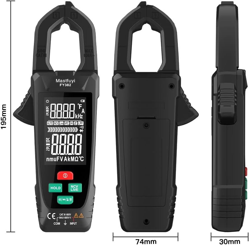
Image: Diagram showing the physical dimensions of the Irfora FY382 Smart Clamp Meter.
Warranty and Support
For warranty information or technical support, please refer to the contact details provided by your retailer or the manufacturer's official website. Specific warranty terms may vary by region and purchase location.