1. Introduction
This manual provides detailed instructions for the installation, operation, and maintenance of the Haofy Universal Sliding Gate Opener Circuit Board (110V). This advanced microcomputer-controlled circuit board offers reliable and convenient operation for sliding gates, featuring remote control capability and robust performance.
Package Contents:
- 1 x Main Board
- 2 x Connecting Wires
- 2 x Remote Controllers
- 1 x User Manual (this document)

Figure 1.1: The Haofy Universal Sliding Gate Opener Circuit Board, accompanied by two remote controls and connecting wires, as included in the package.
2. Specifications
| Feature | Description |
|---|---|
| Item Type | Sliding Gate Opener Circuit Board |
| Material | Electronic components |
| Weight | Approx. 442g (15.59oz) |
| Product Size | Approx. 13x10.4cm (5.1x4.1in) |
| Remote Control Battery | 27A 12V battery x1 (not included) |
| Rated Current | 5A |
| Remote Control Distance | More than 30 meters in open space without obstacles |
| Maximum Remote Units | Up to 40 units |
| Input Voltage | 110V (for this model) |
| Model Number | Haofym02t6ro7cx-11 |
3. Safety Information and Operating Environment
To ensure safe and reliable operation of your Haofy Sliding Gate Opener Circuit Board, please observe the following guidelines:
- Electrical Safety: Always disconnect power before performing any installation, maintenance, or troubleshooting. Work with electricity should only be performed by qualified personnel.
- Moving Parts: Be aware of the moving gate during operation. Keep hands, clothing, and other objects clear of the gate's path to prevent injury.
- Children and Pets: Keep children and pets away from the gate area, especially during operation.
- Emergency Stop: Familiarize yourself with the emergency stop procedure for your gate system.
- Operating Environment:
- Install the circuit board in a well-ventilated area.
- Environmental temperature should be between -30°C to 40°C.
- Avoid dampness or immersion in water.
- Ensure no corrosive gases, liquids, or severe dust are present in the surrounding area.
- Avoid strong vibrations or strong magnetic field interference nearby.
4. Product Components and Overview
This section details the main components of your gate opener system and their functions.
4.1 Circuit Board Layout

Figure 4.1: Overview of the circuit board with key components labeled for identification.
Key components on the circuit board include:
- Learning Key: Used for programming remote controls.
- DIP Switches (1-4): Used to configure various operational settings such as soft start and auto-closing time.
- Motor Rotation Switch: To adjust the direction of motor rotation.
- Resistance Adjustment: For fine-tuning resistance settings.
- Terminal Blocks: For connecting power, motor, limit switches, and other accessories.
- Fuse: 8A/250V for circuit protection.
4.2 Remote Control Overview
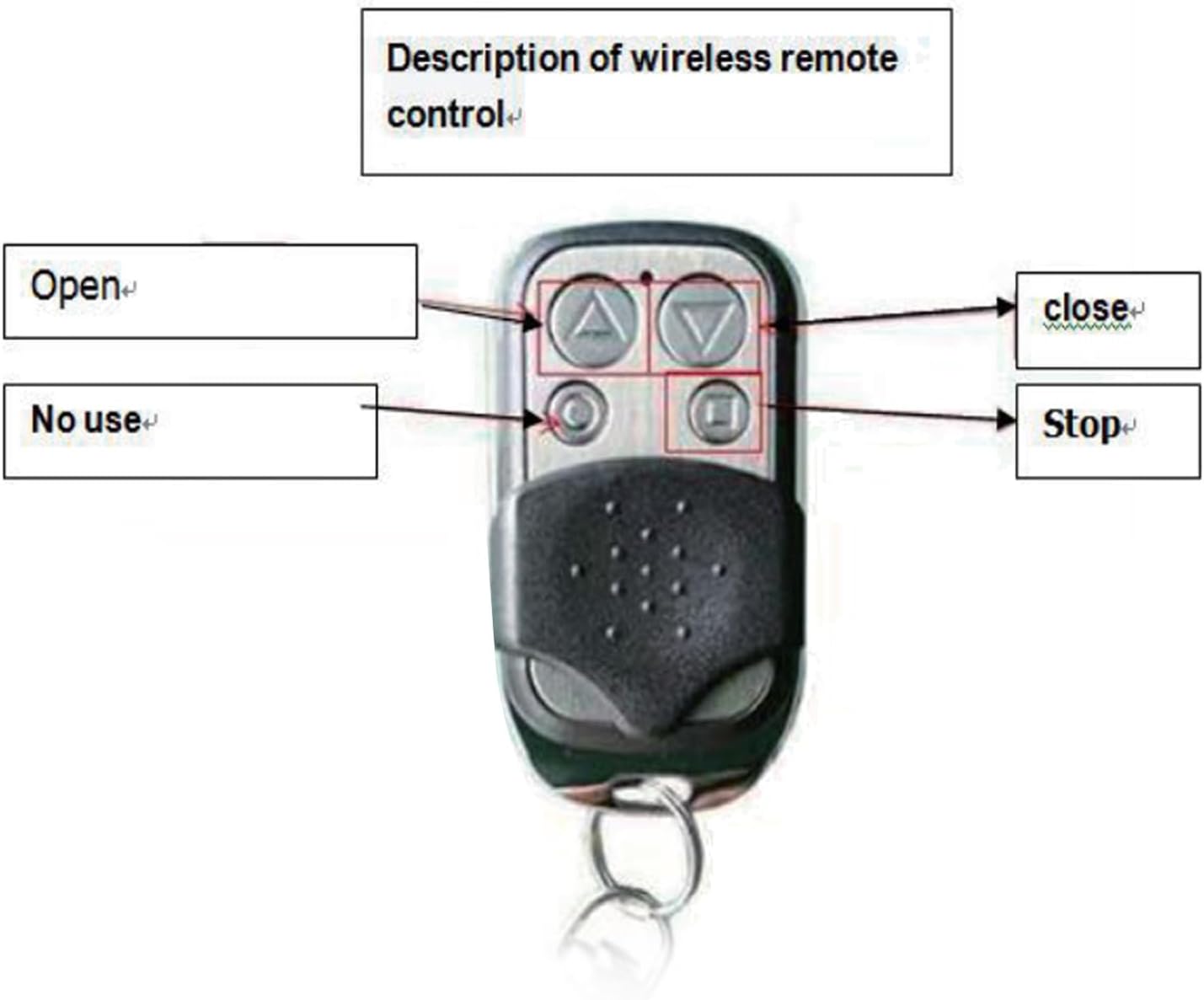
Figure 4.2: The wireless remote control, showing buttons for Open, Close, and Stop functions.
The remote control features dedicated buttons for:
- Open: Initiates the gate opening sequence.
- Close: Initiates the gate closing sequence.
- Stop: Halts the gate's movement immediately.
- Note: One button may be labeled "No use" or serve an unassigned function.
5. Setup and Installation
Proper installation is crucial for the safe and efficient operation of your gate opener. If you are unsure about any steps, consult a qualified electrician or gate technician.
5.1 Wiring Connections
Refer to the circuit board diagram (Figure 4.1) and the terminal block close-up (Figure 5.1) for correct wiring.

Figure 5.1: Close-up of the circuit board's terminal blocks, indicating connection points for various components.
- Power Input: Connect the 110V AC power supply to the designated "INPUT AC110V" terminals (L and N). Ensure proper grounding (PE).
- Motor Connection: Connect the sliding gate motor wires to the "MOTOR" terminals.
- Limit Switches: Connect the gate's limit switches (open, close, common) to the "limit" terminals. The board supports single and double limit configurations.
- Infrared Sensor (Optional): If using an infrared safety sensor, connect it to the "infrared" terminals (2.3).
- Other Accessories: Connect any other accessories (e.g., external buttons, cycle control) to their respective terminals as indicated on the board.
- Output 15VDC: The board provides a 15VDC, 30mA output for auxiliary devices.
5.2 DIP Switch Settings
The DIP switches (Figure 5.2) allow configuration of specific operational parameters.

Figure 5.2: Close-up of the DIP switches (red block) and the learning key on the circuit board.
- DIP Switch 1 (Soft Start):
- ON: Enables soft start function.
- OFF: Disables soft start function.
- DIP Switches 2 & 3 (Auto-closing Time):
- 2 OFF / 3 OFF: Auto-closing after 5 seconds.
- 2 ON / 3 OFF: Auto-closing after 10 seconds.
- 2 OFF / 3 ON: Auto-closing after 20 seconds.
- DIP Switch 4 (Resistance):
- ON: Enables resistance function (likely for obstacle detection sensitivity).
- OFF: Disables resistance function.
Note: Always power off the board before changing DIP switch settings.
5.3 Motor Rotation Direction
Use the "Motor Rotation" switch on the board to ensure the gate opens and closes in the correct direction relative to the remote control commands. Test the gate movement after initial setup and adjust if necessary.
6. Remote Control Programming
The circuit board supports up to 40 remote control units. The remote controls utilize advanced rolling code technology for enhanced security.
6.1 Learning a Remote Control
- Press and hold the "Learning Key" (refer to Figure 5.2) on the circuit board.
- Continue holding until the learning indicator LED lights up.
- While the LED is lit, press any key on the remote control you wish to program for 1 second.
- The learning indicator light will flash, indicating successful coding.
- Release the "Learning Key". The remote control is now programmed.
6.2 Deleting All Remote Control Codes
- Press and hold the "Learning Key" on the circuit board for 12 seconds.
- Release the key. All previously stored remote control codes will be automatically cleared, rendering the original remote controls invalid until re-programmed.
6.3 Remote Control Features
- Rolling Code Technology: Prevents unauthorized access by making it difficult to duplicate the remote control password.
- Smart Programming Design: The remote control automatically stops transmitting after pressing a button for 3 seconds. This prevents interference from accidental prolonged presses and conserves battery power.
7. Operation
Once the circuit board is installed and remote controls are programmed, operating your sliding gate is straightforward.
- Ensure the gate area is clear of any obstructions.
- Use the programmed remote control:
- Press the Open button to open the gate.
- Press the Close button to close the gate.
- Press the Stop button to halt the gate's movement at any point.
- If auto-closing is enabled via DIP switches, the gate will automatically close after the set delay once fully opened.

Figure 7.1: Examples of sliding gate installations where this circuit board can be applied, including residential and commercial settings.
8. Maintenance
Regular maintenance helps ensure the longevity and optimal performance of your gate opener system.
- Visual Inspection: Periodically inspect the circuit board and wiring for any signs of damage, corrosion, or loose connections.
- Cleanliness: Keep the circuit board free from dust and debris. Use a soft, dry brush or compressed air for cleaning.
- Environmental Conditions: Ensure the operating environment continues to meet the specified conditions (temperature, humidity, absence of corrosive elements).
- Remote Control Batteries: Replace remote control batteries (27A 12V) as needed. If the remote control range decreases, it may be an indication of low battery power.
- Gate Mechanism: Regularly check the gate's mechanical components (tracks, wheels, motor) for smooth operation and lubricate as recommended by the gate manufacturer.
9. Troubleshooting
This section addresses common issues you might encounter with your gate opener circuit board.
| Problem | Possible Cause | Solution |
|---|---|---|
| Gate does not respond to remote control. |
|
|
| Gate opens/closes partially or stops unexpectedly. |
|
|
| Gate moves in the wrong direction. | Motor rotation direction is incorrect. | Adjust the "Motor Rotation" switch on the circuit board (Section 5.3). |
| Auto-closing not working or incorrect timing. | DIP switch settings for auto-closing are incorrect. | Verify and adjust DIP switches 2 and 3 (Section 5.2). |
If the problem persists after attempting these solutions, please contact customer support.
10. Warranty and Support
For warranty information and technical support, please refer to the purchase documentation or contact Haofy customer service directly. Ensure you have your product model number (Haofym02t6ro7cx-11) and purchase details available when seeking support.
You can often find support contact information on the official Haofy website or through your retailer.


