
1. Introduction
This manual provides instructions for the proper installation, operation, and maintenance of the Bolisila PSD-S1 S-Type Load Cell. This S-beam design load cell is engineered for precise tension and compression force measurement, offering good stability and mechanical properties suitable for various industrial applications.
- Easy to install and operate.
- Constructed from alloy steel, providing excellent mechanical properties.
- S-type load cell design for accurate tension and compression force measurement with good stability.
- Widely applicable in belt scales, hopper scales, and various engineering force measuring systems.
- Features an S-beam design for stable sensor material and convenient operation.
2. Product Overview
The Bolisila PSD-S1 is an S-type load cell designed for accurate force measurement. Its robust alloy steel construction ensures durability and reliable performance in various industrial applications. The sensor converts mechanical force into an electrical signal, which can then be processed by a compatible indicator or controller.
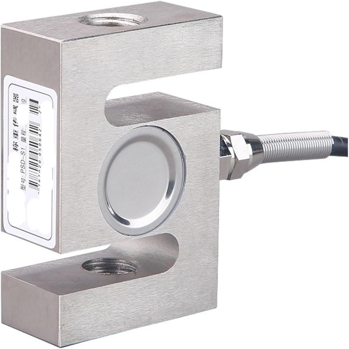
Image: A close-up view of the Bolisila PSD-S1 S-Type Load Cell, showcasing its S-beam design and threaded connection points. The sensor is made of alloy steel and includes a shielded cable for signal transmission.
3. Setup and Installation
3.1 Mounting the Load Cell
The PSD-S1 load cell is designed for both tension and compression applications. Proper mounting is critical for accurate and reliable measurements. Ensure the mounting surface is flat, rigid, and capable of supporting the expected load without deflection. Avoid any side loads or bending moments on the load cell.
- For tension applications, install the load cell such that the force pulls directly along its central axis.
- For compression applications, apply the force directly to the load cell's central axis.
- Use appropriate hardware (e.g., clevises, rod ends) to connect the load cell to the weighing structure, ensuring free movement and preventing binding.
- Tighten all mounting bolts to the manufacturer's recommended torque specifications.

Image: Technical drawing illustrating the dimensions (A, B, C, M) and mounting configuration of the PSD-S1 S-Type Load Cell. A table provides capacity-specific dimensions and weight for various models (e.g., 0.05-0.3t, 0.5t, 1-2t, 3-5t, 10t, 20/30t).
3.2 Electrical Connection
Connect the load cell to a compatible weighing indicator or amplifier using the provided shielded cable. Refer to the wiring diagram of your specific indicator for correct terminal connections. Standard load cell wiring typically involves four or six wires:
- Excitation+ (often Red): Provides positive excitation voltage to the load cell.
- Excitation- (often Black): Provides negative excitation voltage to the load cell.
- Signal+ (often Green): Carries the positive output signal from the load cell.
- Signal- (often White): Carries the negative output signal from the load cell.
- Sense+ (optional, for 6-wire systems, often Blue): Used for remote sensing of excitation voltage to compensate for cable resistance.
- Sense- (optional, for 6-wire systems, often Yellow): Used for remote sensing of excitation voltage to compensate for cable resistance.
Ensure all connections are secure, properly insulated, and protected from environmental factors such as moisture, dust, and electromagnetic interference. Incorrect wiring can lead to inaccurate readings or damage to the load cell or indicator.
4. Operating Principles
The PSD-S1 load cell operates on the principle of strain gauges. When a mechanical force (tension or compression) is applied to the load cell, its alloy steel body deforms elastically. This deformation causes a minute change in the electrical resistance of the internal strain gauges. This change in resistance is then converted into a proportional electrical signal (mV/V) by a Wheatstone bridge circuit within the load cell.
For accurate measurements:
- Allow the load cell to stabilize at the operating temperature before taking measurements.
- Apply loads smoothly and avoid sudden impacts or shock loading.
- Do not exceed the specified safe overload limit to prevent permanent damage.
- Regularly calibrate the entire weighing system (load cell + indicator) according to the indicator's instructions and application requirements.
5. Maintenance
Proper maintenance ensures the longevity and accuracy of your PSD-S1 load cell.
- Cleaning: Keep the load cell and its surroundings clean and free from debris, dust, and corrosive substances. Use a soft, dry cloth for cleaning.
- Cable Inspection: Regularly inspect the load cell cable for any signs of damage, cuts, kinks, or wear. Ensure cable glands are tight to maintain environmental protection.
- Mounting Integrity: Periodically check that all mounting bolts and hardware are securely tightened. Loose connections can lead to inaccurate readings or mechanical failure.
- Environmental Protection: Avoid exposing the load cell to corrosive chemicals, excessive moisture, or extreme temperatures outside its specified operating range. The IP67 rating provides protection against dust and temporary immersion in water, but prolonged exposure should be avoided.
- No Disassembly: Do not attempt to disassemble or modify the load cell. This will void any potential warranty and may cause irreparable damage to the internal components.
6. Troubleshooting
This section addresses common issues you might encounter with the PSD-S1 load cell.
6.1 Inaccurate or Unstable Readings
- Calibration: Ensure the entire weighing system (load cell and indicator) has been properly calibrated according to the indicator's manual. Recalibration may be necessary.
- Mounting: Verify stable mounting. Check for any external forces, vibrations, or binding that might interfere with the measurement. Ensure the load cell is not touching any adjacent structures.
- Overload: Confirm the load cell has not been overloaded beyond its safe capacity. Overloading can cause permanent damage and affect accuracy.
- Environmental Factors: Check for temperature fluctuations, drafts, or electromagnetic interference (EMI) that could affect readings.
6.2 No Output Signal
- Power Supply: Confirm that the weighing indicator or amplifier is powered on and receiving adequate voltage.
- Electrical Connections: Check all electrical connections between the load cell and the indicator for continuity, correct polarity, and secure contact. Look for loose wires or corrosion.
- Cable Damage: Inspect the load cell cable for any breaks, cuts, or severe damage that could interrupt the signal.
- Indicator Fault: If possible, test the load cell with a known working indicator or test the indicator with a known working load cell to isolate the fault.
7. Specifications
The following table details the technical specifications for the Bolisila PSD-S1 S-Type Load Cell:
| Parameter | Value |
|---|---|
| Capacity Range | 20 kg to 2000 kg |
| Rated Output | 2.0 ± 0.004 mV/V |
| Accuracy Class | C2 |
| Non-linearity | 0.02% F.S (Full Scale) |
| Hysteresis | 0.03% F.S |
| Creep in 30 minutes | 0.02% F.S |
| Zero Balance | ±1% F.S |
| Input Resistance | 380 ± 20 Ω |
| Output Resistance | 350 ± 5 Ω |
| Safe Overload | 150% F.S |
| Ultimate Overload | 300% F.S |
| Excitation Voltage | 9~12V DC |
| Max Excitation Voltage | 15V AC/DC |
| Temperature Effect on Span | 0.015% F.S/10°C |
| Temperature Effect on Zero | 0.02% F.S/10°C |
| Compensated Temperature Range | -10°C ~ +40°C |
| Operating Temperature Range | -30°C ~ +65°C |
| Environmental Protection | IP67 |
| Insulation Resistance | 500 MΩ |
| Item Weight (2000kg model) | Approximately 15.9 ounces (450g) |
| Package Dimensions | 1.18 x 0.79 x 0.39 inches |
8. Contact and Support
For further assistance, technical support, or inquiries regarding the Bolisila PSD-S1 S-Type Load Cell, please contact Bolisila customer service through the vendor's official channels or your point of purchase.
Please have your product model (PSD-S1) and any relevant purchase information ready when contacting support.