1. Introduction
This manual provides essential information for the safe and effective installation, operation, and maintenance of the PPOZYLPC LSD11-32A 3-Phase Rotary Cam Changeover Switch. This device is designed for controlling main and auxiliary circuits, including three-phase motors and other electrical loads. Please read this manual thoroughly before installation or operation.
2. Safety Information
WARNING: Electrical work should only be performed by qualified and authorized personnel. Failure to follow these safety instructions may result in electric shock, fire, or serious injury.
- Always disconnect power before installing, servicing, or removing the switch.
- Ensure all wiring complies with local and national electrical codes.
- Verify the switch ratings match the application requirements.
- Do not operate the switch if it appears damaged.
- Use appropriate personal protective equipment (PPE).
3. Product Overview
The PPOZYLPC LSD11-32A is a robust 3-phase rotary cam changeover switch designed for reliable control of electrical circuits. It features a durable construction and a flexible operating handle for ease of use.
3.1 Components
- Rotary Handle: Used to select switch positions (e.g., ON, OFF, or different circuit configurations).
- Switch Body: Contains the internal contacts and switching mechanism.
- Terminals: Connection points for electrical wiring.
- Mounting Plate: For securing the switch to a panel or enclosure.

Figure 1: Front view of the LSD11-32A rotary cam switch, showing the red and yellow handle, and the blue terminal block.

Figure 2: Side view displaying the technical specifications label on the switch body, detailing voltage and current ratings.
4. Technical Specifications
| Parameter | Value |
|---|---|
| Model | LSD11-32A |
| Rated Insulation Voltage (Ui) | 690V |
| Rated Heating Current (Ith) | 32A |
| Rated Operating Voltage (Ue) | 220V, 380V, 500V |
| AC-3 Rated Power (220V/380V/500V) | 5.5kW / 7.5kW / 7.5kW |
| AC-23 Rated Power (220V/380V/500V) | 7.5kW / 11kW / 11kW |
| Package Dimensions | 1.18 x 0.79 x 0.39 inches (approximate) |
| Unit Count | 1.0 Count |
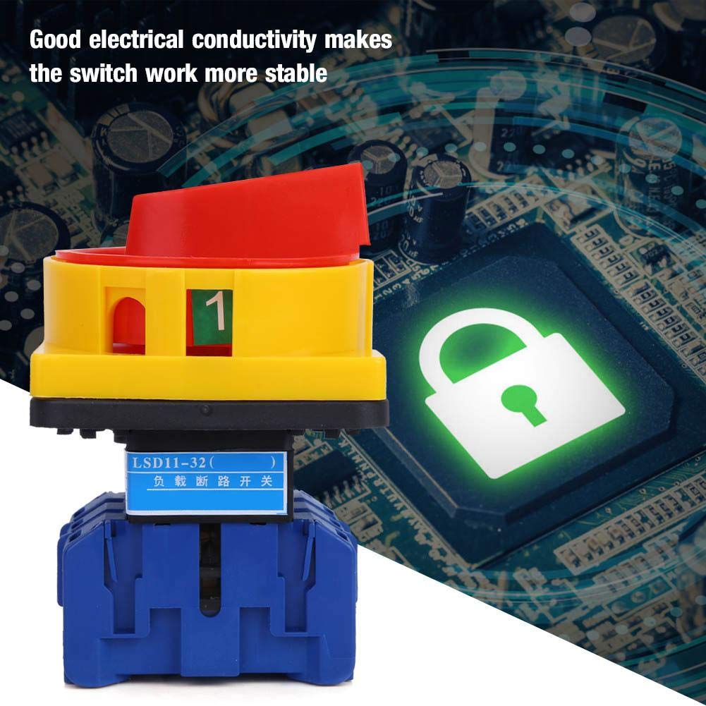
Figure 3: Angled view of the switch, highlighting the terminal connections for wiring.
5. Setup and Installation
Installation of the LSD11-32A switch requires careful attention to electrical safety and adherence to wiring standards. It is strongly recommended that installation be performed by a certified electrician.
5.1 Installation Steps
- Power Disconnection: Ensure all power to the circuit where the switch will be installed is completely disconnected and locked out.
- Mounting: Securely mount the switch to a suitable panel or enclosure using the provided screws. Ensure the mounting surface is stable and free from vibrations.
- Wiring: Connect the main and auxiliary circuit wires to the appropriate terminals on the switch. Refer to the wiring diagram (if provided separately or on the device label) for correct connections. Ensure all connections are tight and secure.
- Verification: Double-check all wiring for correctness and ensure no loose strands or short circuits are present.
- Enclosure: Close and secure the electrical enclosure.
- Power Restoration: Carefully restore power to the circuit.

Figure 4: Bottom view of the switch, illustrating the mounting holes for secure installation.
6. Operating Instructions
The LSD11-32A is a rotary cam changeover switch. Its operation involves rotating the handle to select different circuit states.
6.1 Basic Operation
- Position Indication: The handle typically has clear markings (e.g., "0" for OFF, "1" for ON, or other numerical/symbolic indicators for different circuit configurations).
- Rotation: To change the switch state, firmly grasp the red handle and rotate it clockwise or counter-clockwise to the desired position. The handle will click into place at each defined position.
- Smooth Operation: The handle is designed for flexible and smooth operation. Do not force the handle if it resists movement.
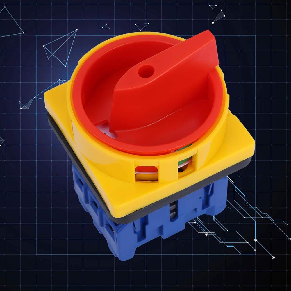
Figure 5: Top view of the switch, showing the red handle in an engaged position, ready for rotation.
7. Maintenance
Regular maintenance ensures the longevity and safe operation of the switch. Always disconnect power before performing any maintenance.
- Visual Inspection: Periodically inspect the switch for any signs of physical damage, discoloration, or loose connections.
- Cleaning: Keep the switch free from dust, dirt, and moisture. Use a dry, lint-free cloth for cleaning. Do not use abrasive cleaners or solvents.
- Terminal Tightness: Check terminal screws for tightness annually to prevent overheating due to loose connections.
- Functionality Test: Occasionally operate the switch to ensure smooth mechanical action and proper electrical switching.
8. Troubleshooting
If the switch is not functioning as expected, consider the following common issues:
| Problem | Possible Cause | Solution |
|---|---|---|
| Switch does not operate smoothly. | Internal obstruction or damage. | Do not force. Inspect for visible damage. If damaged, replace the switch. |
| No power to the load when switch is ON. | Loose wiring, tripped circuit breaker upstream, or internal switch failure. | Disconnect power. Check all wiring connections. Check upstream circuit breakers. If wiring is correct and breaker is reset, the switch may be faulty and require replacement. |
| Switch feels hot during operation. | Overload, loose connections, or internal fault. | Immediately disconnect power. Check for overload conditions. Inspect wiring for loose connections. If the issue persists, replace the switch. |
For issues not listed here or if troubleshooting steps do not resolve the problem, contact qualified electrical personnel.
9. Warranty and Support
PPOZYLPC products are manufactured to high-quality standards. For warranty information or technical support, please refer to the documentation included with your purchase or contact your retailer. Keep your purchase receipt for warranty claims.


