
BSIDE ACM81
BSIDE ACM81 Digital Clamp Multimeter
User Manual
Model: ACM81 | Brand: BSIDE
1. Introduction
The BSIDE ACM81 is a compact and versatile digital clamp multimeter designed for accurate and safe electrical measurements. It features True RMS measurement, auto-ranging capabilities, and a non-contact voltage detection (V-Alert) function, making it suitable for a wide range of applications.
1.1 Key Features
- 1mA AC Current Sensitivity: Capable of measuring AC current down to 1mA via the clamp.
- True RMS Auto-Ranging: Provides accurate readings for non-sinusoidal waveforms and automatically selects the correct measurement range.
- Multi-functional Measurement: Measures AC current, AC/DC voltage, resistance, continuity, diode, and temperature.
- V-Alert Function: Non-contact AC voltage detection for enhanced safety.
- Convenient Design: Features a back clip for portability and a side probe holder for single-hand operation.
- Data Hold: Freezes the displayed reading for easy recording.
- Large LCD with Backlight: Ensures clear readability in various lighting conditions.
- Safety Standards: Conforms to IEC-61010-1, IEC-61010-2-030, IEC-61010-2-032, IEC-61010-2-033 standards, with CAT III 300V and CAT II 600V over-voltage protection.
1.2 Package Contents
Upon opening the package, verify that all items are present and undamaged:
- 1 x BSIDE ACM81 Digital Clamp Meter
- 1 x Pair of Test Probes (Red and Black)
- 1 x Thermocouple (for temperature measurement)
- 1 x Carrying Case
- 1 x Screwdriver (for battery compartment)
- 1 x User Manual (this document)

Figure 1.1: Package Contents of the BSIDE ACM81
2. Safety Information
To ensure safe operation and avoid personal injury or damage to the meter, please read all safety instructions carefully before use. Always adhere to local and national safety codes.
- Do not exceed the maximum input values specified for each measurement range.
- Exercise extreme caution when working with voltages above 30V AC RMS, 42V peak, or 60V DC. These voltages pose a shock hazard.
- Before measuring current with the clamp, ensure the circuit is de-energized if possible, and always wear appropriate personal protective equipment (PPE).
- Never use the meter if it appears damaged or if the insulation on the test leads is compromised.
- Ensure the battery cover is securely closed before operation.
- Do not operate the meter in explosive gas, vapor, or dust environments.
- The meter is rated for CAT III 300V and CAT II 600V. Do not use it for measurements exceeding these categories.
- Remove test leads from the circuit before changing functions.
3. Components and Controls
Familiarize yourself with the parts of your BSIDE ACM81 clamp multimeter:
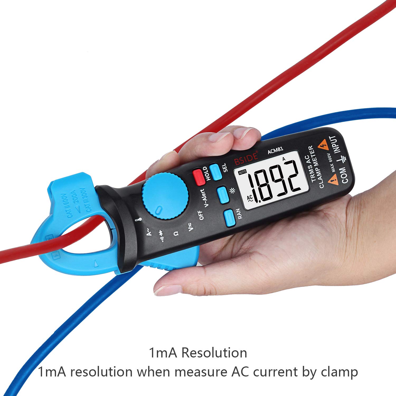
Figure 3.1: BSIDE ACM81 Components Overview
- V-Alert Sensor: Detects non-contact AC voltage.
- Clamp: Used for non-contact AC current measurement.
- Probe Holder: Conveniently stores test probes when not in use.
- Trigger: Opens and closes the clamp jaw.
- Function Switch: Rotary dial to select measurement modes (AC Current, Voltage, Resistance/Continuity/Diode, Temperature, OFF).
- Data Hold (HOLD) Button: Freezes the current reading on the display.
- Function Selection (SEL) Button: Toggles between sub-functions within a rotary switch position (e.g., Resistance, Continuity, Diode).
- Manual/Auto Switch (RAN) Button: Toggles between auto-ranging and manual ranging modes.
- Backlight Button (*): Activates or deactivates the LCD backlight.
- LCD Display: Shows measurement readings, units, and indicators.
- COM Port: Common (negative) input terminal for test leads.
- INPUT Port: Positive input terminal for test leads (for voltage, resistance, etc.).
4. Setup
4.1 Battery Installation
The BSIDE ACM81 requires two 1.5V AAA batteries (not included). Follow these steps to install them:
- Ensure the meter is turned OFF.
- Locate the battery compartment on the back of the meter.
- Use the provided screwdriver to loosen the screw securing the battery cover.
- Remove the battery cover.
- Insert two AAA batteries, observing the correct polarity (+ and -) as indicated inside the compartment.
- Replace the battery cover and tighten the screw securely.

Figure 4.1: Battery Installation
5. Operating Instructions
5.1 Power On/Off and Auto Power Off
- To turn on the meter, rotate the Function Switch from the 'OFF' position to any desired measurement function.
- To turn off the meter, rotate the Function Switch to the 'OFF' position.
- The meter features an Auto Power Off function to conserve battery life. It will automatically power off after approximately 15 minutes of inactivity.
5.2 AC Current Measurement (Clamp)
This meter can measure AC current without breaking the circuit, using its clamp jaw.
- Rotate the Function Switch to the 'A~' position.
- Press the trigger to open the clamp jaw.
- Enclose only one conductor (live or neutral) within the clamp jaw. Do not clamp around multiple conductors as this will result in an inaccurate reading (the magnetic fields will cancel out).
- Release the trigger to close the clamp jaw securely around the conductor.
- Read the AC current value on the LCD display. The meter has 1mA sensitivity for precise readings.

Figure 5.1: Measuring AC Current with 1mA Resolution

Figure 5.2: Easy Clamp Control
5.3 Voltage Measurement (AC/DC)
To measure AC or DC voltage:
- Insert the red test lead into the 'INPUT' terminal and the black test lead into the 'COM' terminal.
- Rotate the Function Switch to the 'V=' (DC Voltage) or 'V~' (AC Voltage) position. If the symbol is 'V', press the 'SEL' button to toggle between AC and DC voltage.
- Connect the test probes in parallel to the circuit or component you wish to measure.
- Read the voltage value on the LCD display.

Figure 5.3: Battery and AC Voltage Measurement
5.4 Resistance, Continuity, and Diode Measurement
These functions are typically grouped under one rotary switch position.
- Insert the red test lead into the 'INPUT' terminal and the black test lead into the 'COM' terminal.
- Rotate the Function Switch to the 'Ω' (Ohm) position.
- Press the 'SEL' button to cycle through Resistance (Ω), Continuity (buzzer symbol), and Diode (diode symbol) modes.
- For Resistance: Connect the probes across the component. Read the resistance value.
- For Continuity: Connect the probes across the circuit. If resistance is less than 30Ω, the buzzer will sound.
- For Diode: Connect the red probe to the anode and the black probe to the cathode. The display will show the forward voltage drop. Reverse the probes to check for open circuit.
5.5 Temperature Measurement
To measure temperature:
- Insert the thermocouple into the 'INPUT' and 'COM' terminals, observing polarity (usually red to INPUT, black to COM).
- Rotate the Function Switch to the temperature symbol (℃/℉).
- Press the 'SEL' button to toggle between Celsius (℃) and Fahrenheit (℉).
- Place the thermocouple tip on or near the object whose temperature you wish to measure.
- Read the temperature value on the LCD display.
5.6 V-Alert (Non-Contact Voltage Detection)
The V-Alert function allows for quick detection of AC voltage without direct contact, enhancing safety.
- Rotate the Function Switch to the 'V-Alert' position.
- Move the V-Alert sensor (located at the top of the clamp jaw) close to the conductor or outlet you suspect has AC voltage.
- The meter will emit an audible beep and the V-Alert indicator on the display will illuminate if AC voltage is detected. The frequency of beeps and indicator intensity may increase with stronger voltage.

Figure 5.4: V-Alert (Non-Contact Voltage Detection)
5.7 Data Hold Function
The Data Hold function allows you to freeze the current reading on the display, which is useful when taking measurements in hard-to-reach areas or when you need to record the value.
- While taking a measurement, press the 'HOLD' button. The current reading will be frozen on the display, and a 'HOLD' indicator will appear.
- Press the 'HOLD' button again to release the reading and return to live measurement mode.
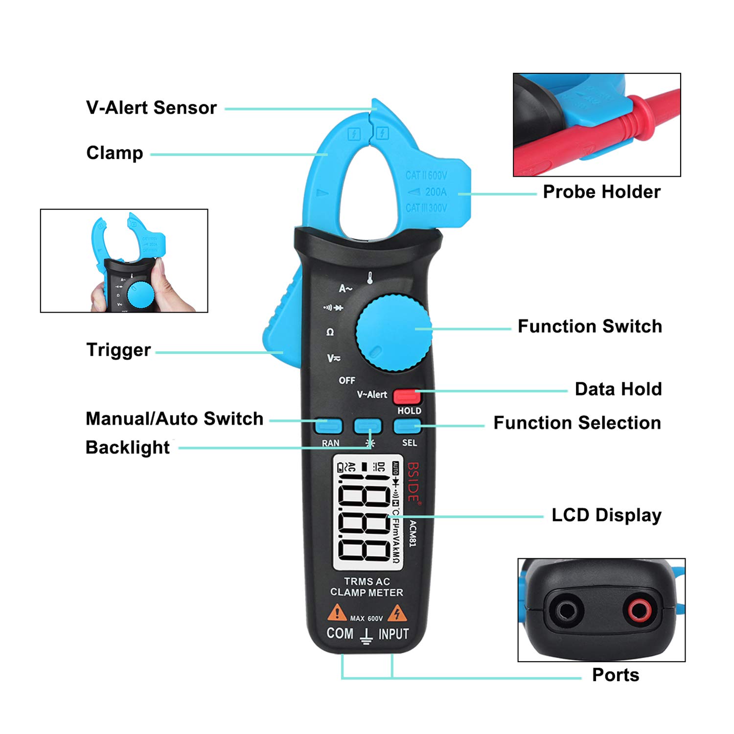
Figure 5.5: Data Hold Function
6. Specifications
| Parameter | Specification |
|---|---|
| Display | 2000 counts |
| AC Current (Clamp) | 2A/20A/200A (Resolution: 0.001A/0.01A/0.1A, Accuracy: ±2.5%+5 counts) |
| DC Voltage | 200mV/2V/20V/200V/600V (Resolution: 0.1mV/0.001V/0.01V/0.1V/1V, Accuracy: ±1.0%+3 counts) |
| AC Voltage | 200mV/2V/20V/200V/600V (Resolution: 0.1mV/0.001V/0.01V/0.1V/1V, Accuracy: ±1.0%+3 counts) |
| Resistance | 200Ω/2kΩ/20kΩ/200kΩ/2MΩ (Accuracy: ±1.0%+3 counts) 20MΩ (Accuracy: ±1.2%+20 counts) |
| Continuity Buzzer | Sounds if resistance is less than 30Ω |
| Diode | Shows positive voltage value of diode approximately |
| Temperature | -20℃~500℃ / -4℉~932℉ (Resolution: 1℃/2℉, Accuracy: ±2.0%+2 counts) |
| Jaw Capacity | 20mm |
| Power | 2 x 1.5V AAA batteries |
| Dimensions | 179mm x 67mm x 36mm (7.05 x 2.64 x 1.54 inches) |
| Weight | 137g (4.9 ounces) |
| Safety Rating | CAT III 300V, CAT II 600V, Pollution Degree II |
7. Maintenance
7.1 Cleaning
To maintain the accuracy and longevity of your meter:
- Wipe the case with a damp cloth and mild detergent. Do not use abrasives or solvents.
- Keep the terminals and clamp jaw clean and free of dust or debris.
- Ensure the meter is completely dry before use.
7.2 Battery Replacement
When the battery indicator appears on the LCD, the batteries are low and should be replaced immediately to ensure accurate readings. Refer to Section 4.1 for battery installation steps.
7.3 Storage
If the meter is not to be used for an extended period, remove the batteries to prevent leakage and store the meter in its carrying case in a cool, dry place, away from direct sunlight and extreme temperatures.
8. Troubleshooting
If you encounter issues with your BSIDE ACM81, refer to the following common problems and solutions:
| Problem | Possible Cause | Solution |
|---|---|---|
| Meter does not turn on | Dead or incorrectly installed batteries | Check battery polarity; replace batteries. |
| No reading or 'OL' displayed | Overload, open circuit, or incorrect range/function | Ensure circuit is complete; select appropriate function/range; check if value exceeds meter's maximum. |
| Inaccurate readings | Low battery, dirty probes/terminals, external interference | Replace batteries; clean probes/terminals; move away from strong electromagnetic fields. |
| Continuity buzzer not sounding | Resistance too high, or not in continuity mode | Ensure resistance is below 30Ω; press SEL to select continuity mode. |
| V-Alert not detecting | No AC voltage present, or sensor not close enough | Verify AC voltage presence; ensure sensor is directly over the conductor. |
9. Warranty and Support
BSIDE products are manufactured to high-quality standards. For specific warranty information, please refer to the warranty card included with your product or contact BSIDE customer support directly. If you require technical assistance or have questions regarding the operation of your ACM81 Digital Clamp Multimeter, please reach out to the manufacturer's support channels.
For further assistance, please visit the official BSIDE website or contact their customer service department.
Related documentsACM81


Ask a question about this manual
Ask about setup, troubleshooting, compatibility, parts, safety, or missing instructions. Manuals+ will review the question and use this page’s manual context to help answer it.