1. Overview
The DROK DC-DC Buck-Boost Converter is a versatile power module designed to provide stable voltage and current output from a wide input range. It features an LCD display for real-time monitoring and adjustable output parameters, making it suitable for various electronic projects and applications. This manual provides essential information for safe and effective operation.
2. Specifications
Below are the detailed technical specifications for the DROK DC-DC Buck-Boost Converter:
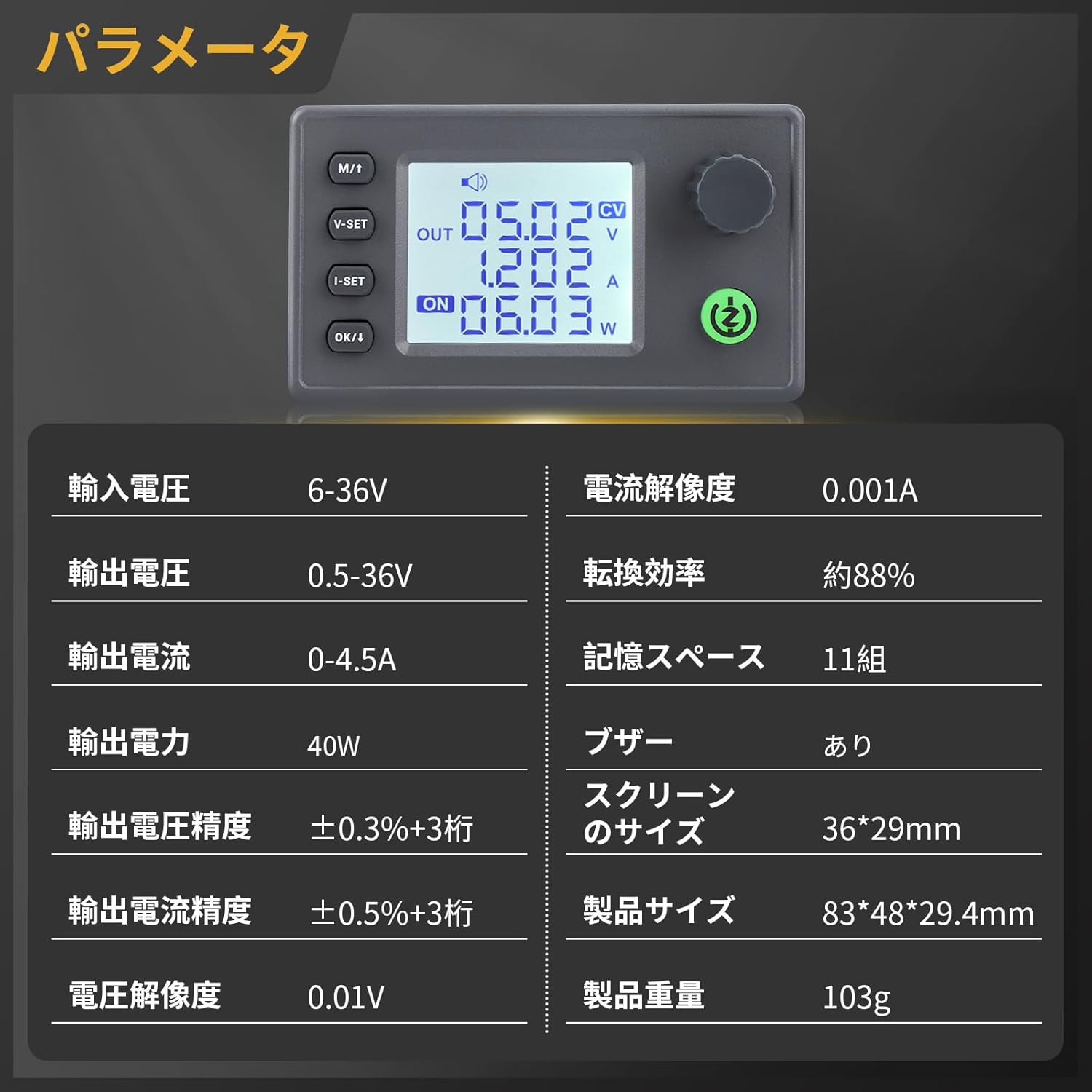
Image: Detailed specifications of the converter, including input/output voltage, current, power, and display size.
| Parameter | Value |
|---|---|
| Input Voltage Range | DC 6-36V |
| Output Voltage Range | DC 0.5-36V |
| Output Current | 0-4.5A (Adjustable) |
| Output Power | 40W |
| Voltage Resolution | 0.01V |
| Current Resolution | 0.001A |
| Voltage Accuracy | ±0.3% + 3 digits |
| Current Accuracy | ±0.5% + 3 digits |
| Conversion Efficiency | Approx. 88% |
| Memory Storage | 11 groups |
| Buzzer | Included |
| Screen Size | 36*29mm |
| Product Size | 83*48*29.4mm |
| Product Weight | 103g |
3. Key Features
- Wide Input/Output Range: Supports DC 6-36V input and adjustable DC 0.5-36V output with 0-4.5A current, providing stable power for diverse applications.
- Enhanced Cooling: Features a dedicated 5V fan port for optional fan installation (supports 30mm fans) to improve heat dissipation. The fan operates under smart temperature control, activating only when current is high and temperature rises.
- Multi-functional Interface: An integrated buzzer provides audible feedback for key operations and alerts, ensuring quick recognition of actions and potential issues.
- Comprehensive Protection: Equipped with multiple safety features including reverse connection protection, reverse current protection, undervoltage protection (LVP), overvoltage protection, overcurrent protection, overtemperature protection, and overpower protection.
- LCD Display: Clear LCD screen displays real-time voltage, current, power, temperature, and other parameters.

Image: Internal components highlighting the built-in buzzer, 5V fan port, and plug-in terminals for easy installation and replacement.
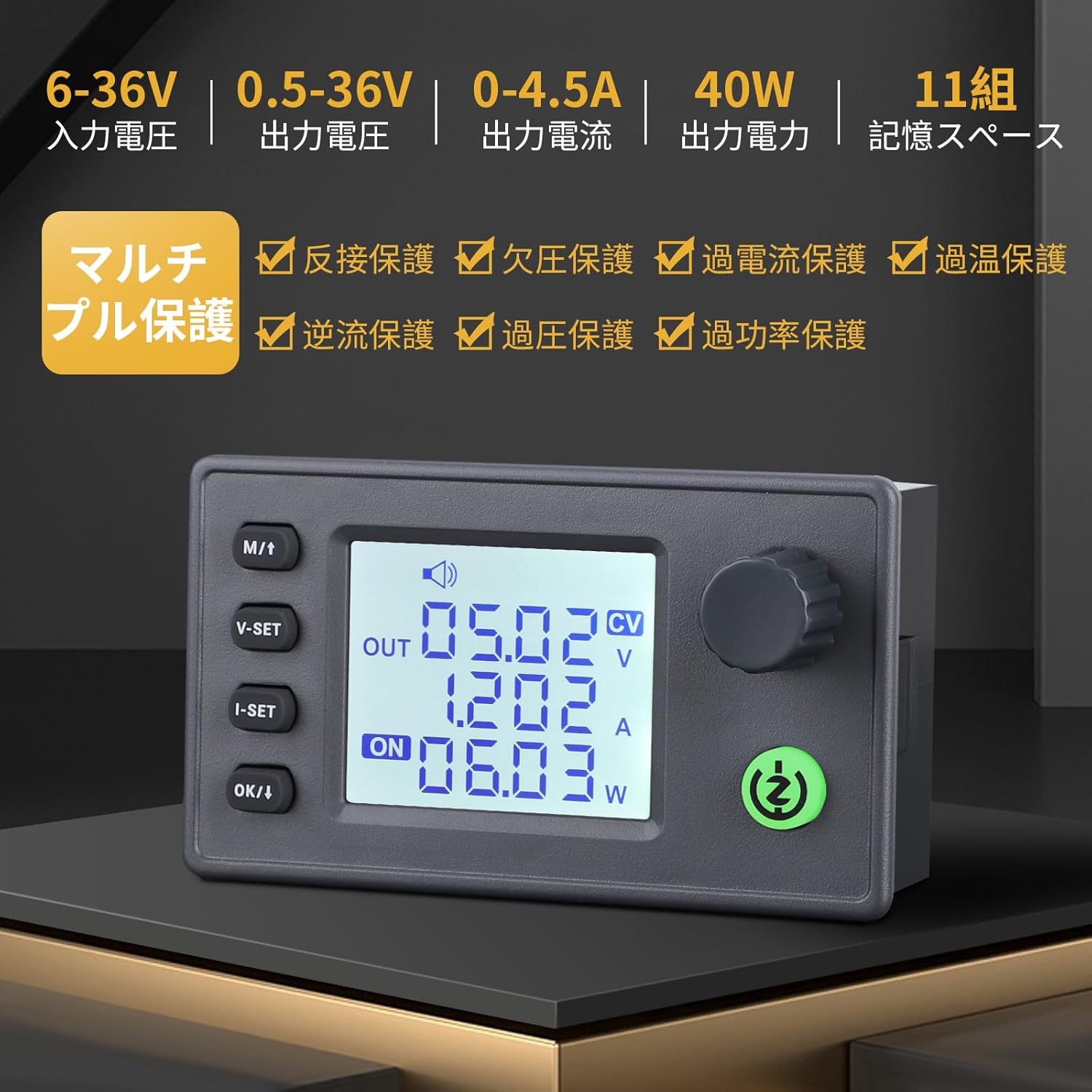
Image: Visual representation of the multi-protection features including reverse connection, reverse current, undervoltage, overvoltage, overcurrent, overtemperature, and overpower protection.
4. Setup and Assembly
This section guides you through the physical setup and assembly of your DROK Buck-Boost Converter. Ensure all components are present before starting.
4.1 Component Identification
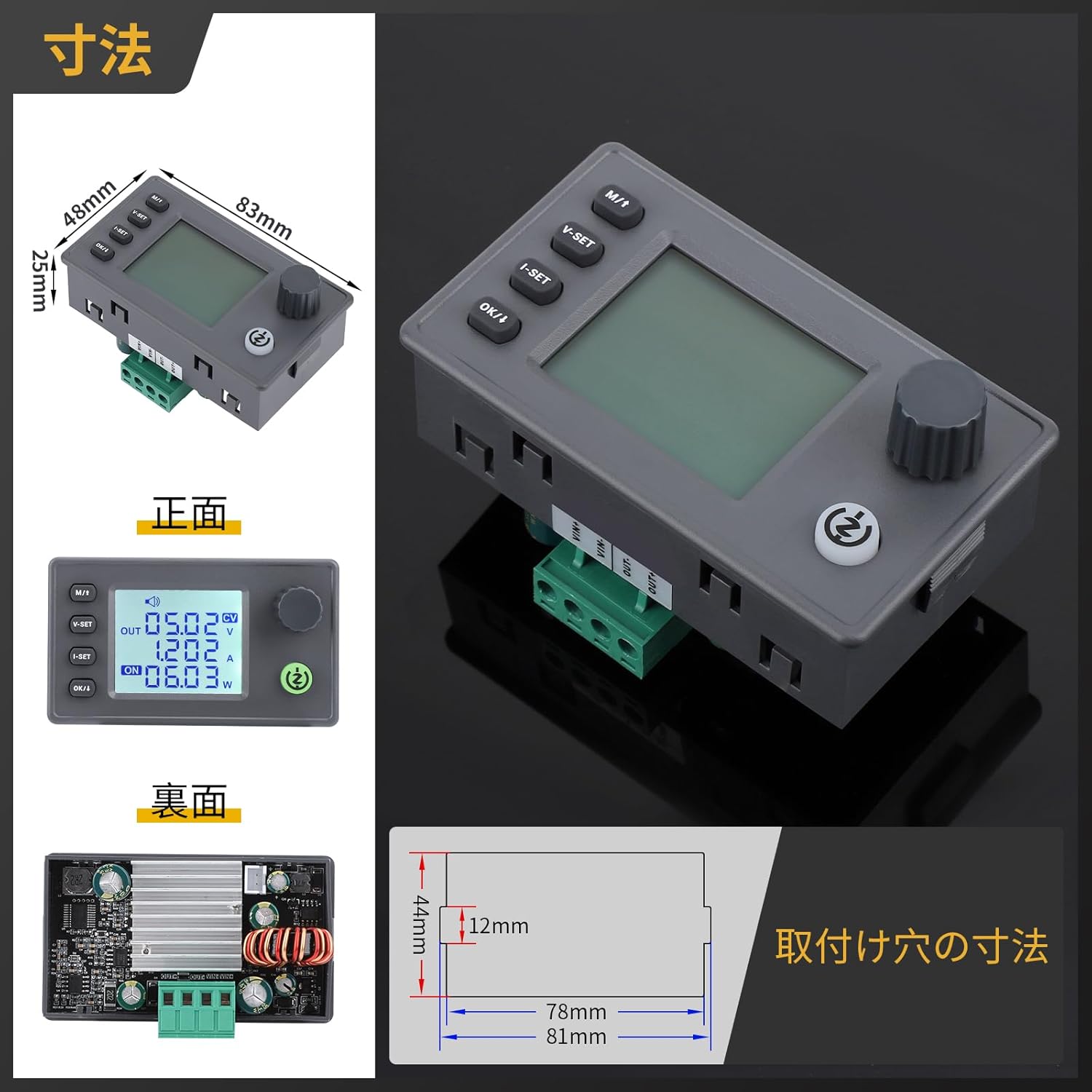
Image: Front, back, and side views of the converter with key dimensions and mounting hole measurements.
4.2 Assembly (if applicable)
If your converter came as a module requiring case assembly, follow these general steps. Refer to the video for visual guidance.
- Carefully remove any protective films from the acrylic case panels.
- Attach the standoffs to the main circuit board.
- Align the bottom acrylic panel with the standoffs and secure it with screws.
- Place the main circuit board onto the bottom panel, ensuring all ports and buttons align with the case openings.
- Attach the side panels and then the top panel, securing them with the remaining screws.
Video: Demonstration of assembling a buck-boost converter module into an acrylic case. This video provides a general guide for module assembly.
4.3 Wiring
Connect the input power source to the 'IN' terminals and your load to the 'OUT' terminals. Ensure correct polarity (+ to + and - to -) to prevent damage. The module includes reverse connection protection, but it is always best practice to double-check wiring.
5. Operating Instructions
This section details how to operate your DROK Buck-Boost Converter, including adjusting voltage and current, and understanding the display modes.
5.1 Button Functions

Image: Diagram illustrating the function of each button and knob on the converter.
- SW (Short Press): Toggle between input voltage and output voltage display.
- SW (Long Press): Enter/Exit the settings menu.
- V-SET (Short Press): Adjust voltage setting.
- I-SET (Short Press): Adjust current setting.
- OK/I (Short Press): Toggle display of output power (W), capacity (Ah), energy (Wh), time (h), and temperature (°C).
- OK/I (Long Press): Enter sleep mode and shut down.
- Rotary Encoder (Short Press): Toggle output ON/OFF.
- Rotary Encoder (Long Press): Enable/Disable lock function.
- Rotary Encoder (Rotate Left): Decrease numerical value.
- Rotary Encoder (Rotate Right): Increase numerical value.
5.2 Adjusting Voltage and Current
To adjust the output voltage or current, first ensure the output is OFF. Use the V-SET or I-SET buttons to select the parameter you wish to change, then use the rotary encoder to adjust the value. Short press the rotary encoder to turn the output ON/OFF.
Video: A demonstration of how to adjust the voltage and current settings on a similar DC power supply unit. Note that the interface may differ slightly from your specific buck-boost converter model.
5.3 Display Modes

Image: Explains various display modes on the LCD, including input/output voltage, current, power, capacity, energy, time, and temperature.
The LCD can display various parameters. Use the OK/I button to cycle through different display modes such as output power (W), accumulated capacity (Ah), accumulated energy (Wh), operating time (h), and internal temperature (°C).
5.4 Output Control
The output can be turned ON or OFF by a short press of the rotary encoder. When the output is ON, the "ON" indicator light will illuminate. When OFF, the light will be off.
Video: A general overview of a DROK DC-DC buck-boost converter, demonstrating basic operation and display functions. Please note that this video features a 35W model, while your product is 40W.
Video: A demonstration of an automatic buck-boost board from DROK, showcasing its functionality. This video features a 5.5-30V to 0.5-30V 3A 50W model, which is similar but not identical to your product.
6. Maintenance
- Cleaning: Keep the module clean and free from dust. Use a soft, dry cloth for cleaning. Avoid using liquids or abrasive cleaners.
- Ventilation: Ensure adequate airflow around the module, especially if an external fan is installed. Do not block ventilation holes.
- Storage: Store the converter in a dry, cool environment when not in use.
- Inspection: Periodically check wiring connections for tightness and signs of wear or damage.
7. Troubleshooting
| Problem | Possible Cause | Solution |
|---|---|---|
| No display/No power | Input power not connected or insufficient; faulty wiring. | Check input power supply and connections. Ensure input voltage is within 6-36V. |
| Output voltage/current cannot be adjusted | Output is ON; parameters are locked; rotary encoder issue. | Turn output OFF before adjusting. Long press rotary encoder to unlock. Check encoder functionality. |
| Buzzer sounds frequently | Protection mechanism triggered (e.g., overcurrent, overtemperature, undervoltage). | Check load for short circuits or excessive current draw. Ensure adequate cooling. Verify input voltage is stable and sufficient. Reduce output power if necessary. |
| LVP (Low Voltage Protection) triggered | Input voltage is below the set LVP threshold or too low for operation. | Increase the input voltage to a sufficient level for normal operation. |
8. Warranty and Support
For warranty information and technical support, please refer to the product packaging or contact DROK customer service directly. Keep your purchase receipt as proof of purchase.
You can often find additional support and resources on the official DROK website or through the retailer where you purchased the product.


