
1. Introduction
This manual provides essential information for the safe and efficient installation, operation, and maintenance of your Aoleaby DC Brush Gear Motor. Please read this manual thoroughly before using the product to ensure proper function and to prevent damage or injury. This motor is designed for applications such as electric wheelchairs, offering reliable performance with its geared design.
2. Product Overview
The Aoleaby DC Brush Gear Motor is a robust and efficient power unit available in 250W and 350W configurations, operating at 24V or 36V. It features a brush motor design with an integrated brake, making it suitable for applications requiring precise control and stopping capabilities, such as electric wheelchairs. The gear reduction system provides high torque at lower speeds, enhancing its utility in mobility devices.
Key Features:
- High Efficiency: Converts electrical energy into mechanical energy with minimal losses.
- Variable Speed Control: Allows for precise speed adjustments to meet specific operational requirements.
- Compact Size: Designed to be lightweight and easy to integrate into various systems.
- Reliability and Durability: Constructed for long-term performance with minimal maintenance.
- Integrated Brake: Enhances safety and control in applications like wheelchairs.
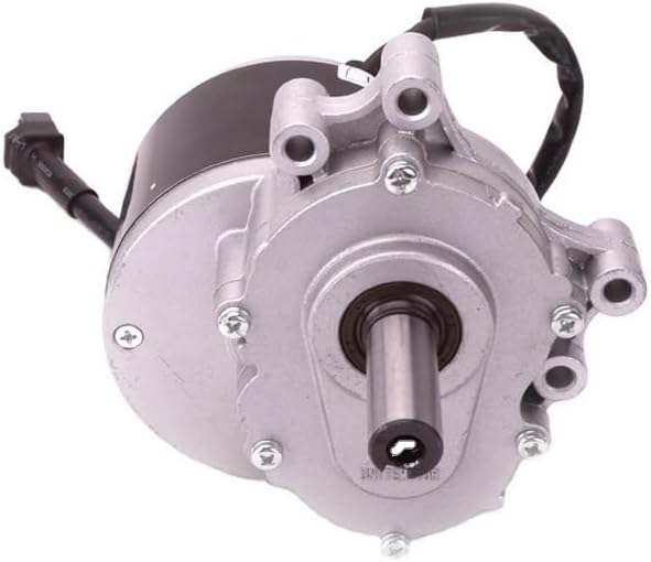
Figure 1: Top-down view of the Aoleaby DC Brush Gear Motor, showing the main casing, output shaft, and electrical connection.
3. Safety Information
Always observe the following safety precautions to prevent injury or damage to the motor and associated equipment:
- Ensure the power supply matches the motor's rated voltage (24V or 36V).
- Disconnect power before performing any installation, maintenance, or troubleshooting.
- Avoid touching moving parts during operation.
- Do not operate the motor in wet or excessively dusty environments unless specifically designed for such conditions.
- Securely mount the motor to prevent vibration and ensure stable operation.
- Consult a qualified technician for complex installations or repairs.
4. Setup and Installation
Proper installation is crucial for the motor's performance and longevity. This motor is typically used in wheelchair drive systems.
4.1 Mounting the Motor
- Identify the appropriate mounting points on your application (e.g., wheelchair frame). The motor features multiple mounting holes on its casing.
- Align the motor with the drive mechanism (e.g., wheel axle).
- Secure the motor using appropriate bolts and washers. Ensure all fasteners are tightened to the manufacturer's specifications to prevent loosening during operation.
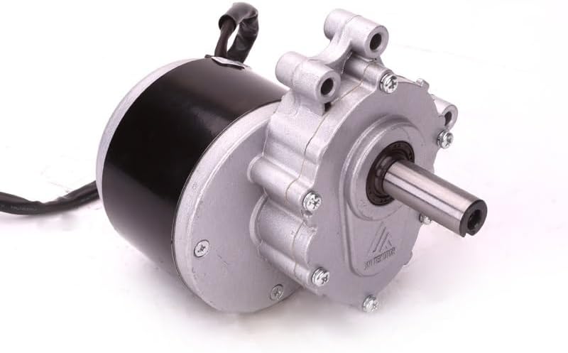
Figure 2: Angled view of the motor, highlighting the various mounting points on the gear housing.
4.2 Electrical Connections
The motor requires a DC power supply matching its rated voltage (24V or 36V). It is a brush motor, and polarity must be observed for correct rotation direction. The motor also includes an integrated brake, which will have its own control wires.
- Connect the main power leads from your controller/battery to the motor's power input. Typically, red is positive (+) and black is negative (-).
- Connect the brake control wires to the appropriate outputs on your motor controller. Refer to your controller's manual for specific wiring diagrams.
- Ensure all connections are secure and insulated to prevent short circuits.

Figure 3: Side view of the motor, illustrating the robust electrical wiring exiting the motor housing.
5. Operating Instructions
Once properly installed and wired, the motor can be operated via a compatible DC motor controller. The controller allows for variable speed control and activation of the integrated brake.
- Ensure all safety checks are complete before applying power.
- Turn on the main power supply to the motor controller.
- Use the controller's input (e.g., joystick, throttle) to gradually increase motor speed.
- To stop the motor, reduce the speed to zero or activate the brake function through the controller. The integrated brake will engage to hold the position.
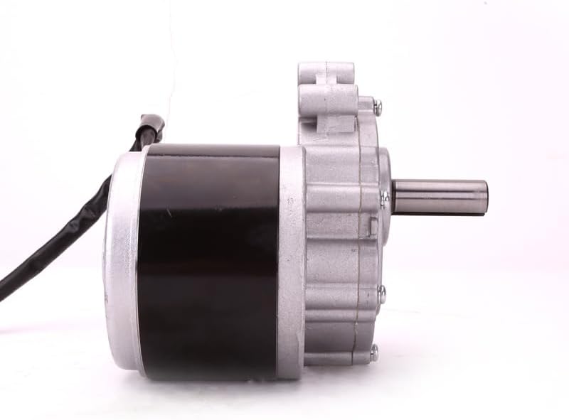
Figure 4: Another side view of the motor, providing a clear perspective of the motor body and the gear reduction housing.
6. Maintenance
The Aoleaby DC Brush Gear Motor is designed for minimal maintenance due to its robust construction. However, regular inspections can extend its lifespan and ensure optimal performance.
- Cleaning: Periodically clean the exterior of the motor to remove dust and debris. Use a dry cloth or soft brush. Avoid using water or solvents directly on the motor.
- Inspection: Regularly check all electrical connections for tightness and signs of wear or corrosion. Inspect mounting bolts to ensure they are secure. Listen for unusual noises during operation, which could indicate an issue.
- Brush Inspection (if applicable): As a brush motor, the carbon brushes will wear over time. If the motor performance degrades, consult a qualified technician for brush inspection and replacement.

Figure 5: Front view of the motor, clearly showing the output shaft and the electrical connector for power and brake control.
7. Troubleshooting
If you encounter issues with your motor, perform the following basic checks:
- Motor Not Running:
- Check power supply: Ensure the battery or power source is charged and connected correctly.
- Check electrical connections: Verify all wires are securely connected and free from damage.
- Check controller: Ensure the motor controller is functioning correctly and receiving input.
- Unusual Noise or Vibration:
- Check mounting: Ensure the motor is securely mounted and not loose.
- Inspect for obstructions: Look for any foreign objects interfering with the motor or gear mechanism.
- Internal issue: If noise persists, discontinue use and consult a qualified technician.
- Motor Overheating:
- Check load: Ensure the motor is not operating under excessive load.
- Check ventilation: Ensure the motor has adequate airflow for cooling.
For issues not resolved by these steps, contact customer support or a qualified service professional.
8. Specifications
| Parameter | Value |
|---|---|
| Product Numbers | MY1016Z / ZD101AZ1 |
| Rated Power | 250 W / 350 W |
| Electricity Voltage | 24 V / 36 V |
| No-load Current | 4.0 A |
| No-load Speed | 75/120 RPM (250W) / 160 RPM (350W) |
| Rated Torque | 0.64 N.m (250W) / 0.98 N.m (350W) |
| Rated Speed | 2400 RPM (250W) / 3700 RPM (350W) |
| Rated Current | 13.7 A (250W) / 14.8 A (350W) |
| Motor Efficiency | 70% (250W) / 76% (350W) |
| Work System | S2: 60 (Short-time duty) |
| Insulation Class | E |
| Reduction Ratio | 37.98:1 |
| Adaptation Range | Wheelchair motor |
| Item Weight | 8.82 pounds (approx. 4 kg) |
| Package Dimensions | 1.18 x 0.79 x 0.39 inches (approx. 3 x 2 x 1 cm) |
9. Warranty and Support
For warranty information and technical support, please refer to the documentation provided at the time of purchase or contact your seller directly. Keep your purchase receipt as proof of purchase.