1. Introduction
The SpeedyBee TX Ultra FPV VTX (Video Transmitter) is a high-performance, compact video transmission module designed for FPV (First Person View) drones. It offers adjustable power output, ranging from PIT mode to 1.6W, ensuring clear and reliable video feed for various flying environments. With support for IRC Tramp protocol and Pit Mode, it provides advanced control and convenience for FPV enthusiasts.

Image: The SpeedyBee TX Ultra FPV VTX: TX1600 module, showing its compact size and pinout labels for 5V OUT, GND, 7-28V, IRC, GND, and VIDEO.
2. Features
- Adjustable Power Output and High-efficiency Heat Sink: 5.8GHz 48CH PIT / 25mW / 200mW / 400mW / 800mW switchable, with a maximum output of 1.6W.
- IRC Tramp Protocol Support: Allows modification of video transmitter parameters through a remote control or the SpeedyBee App.
- Pit Mode Support: Enables powering up the aircraft for parameter adjustment without disturbing other pilots in the same field.
- Side LED Indicators: Three color LED indicators provide intuitive status feedback for channel, band, and power settings.
- Simple Installation: Features a 20x20mm mounting hole distance for convenient stacking with other electronic components.

Image: The SpeedyBee TX Ultra FPV VTX mounted on a drone frame, highlighting its compact design and 20x20mm mounting holes for seamless integration.
3. Package Contents
The SpeedyBee TX Ultra FPV VTX package includes the following items:
- TX ULTRA * 1 (SpeedyBee TX Ultra FPV VTX module)
- MMCX to SMA Cable * 1 (Cable for connecting the VTX to an SMA antenna)
- MMCX antenna * 1 (Antenna with MMCX connector)
- 1.0mm 4pin Cable * 1 (4-pin cable for power and signal connections)

Image: Contents of the SpeedyBee TX Ultra package, showing the TX Ultra module, MMCX to SMA cable, MMCX antenna, and a 1.0mm 4-pin cable.
4. Specifications
| Specification | Value |
|---|---|
| Brand | SPEEDY BEE |
| Model Name | TX Ultra FPV VTX: TX1600 |
| Power Output | PIT / 25mW / 200mW / 400mW / 800mW / 1.6W (Max) |
| Frequency | 5.8GHz, 48 Channels |
| Mounting Hole Distance | 20 x 20 mm |
| Antenna Connector | MMCX |
| Protocol Support | IRC Tramp, Pit Mode |
| Item Weight | ~7g (module only, based on product title) / 30g (package weight) |
| Package Dimensions | 6.8 x 5.2 x 2.4 cm |
5. Setup and Installation
5.1 Wiring Connections
The SpeedyBee TX Ultra supports both JST socket and direct pad connections. Ensure correct polarity and pin assignments when connecting to your flight controller or power distribution board.
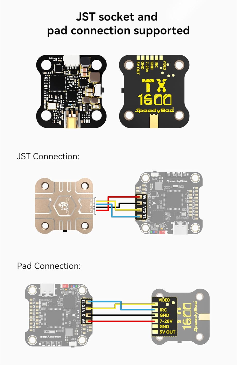
Image: Diagrams illustrating JST socket and direct pad connection methods for the SpeedyBee TX Ultra, showing pin assignments for 5V OUT, GND, 7-28V, IRC, GND, and VIDEO.
JST Connection:
- Connect the provided 1.0mm 4-pin cable to the JST socket on the VTX.
- Match the wire colors to the corresponding pins on your flight controller or power source:
- 5V OUT: For powering external devices (e.g., FPV camera).
- GND: Ground connection.
- 7-28V: Main power input for the VTX.
- IRC: IRC Tramp protocol signal line for VTX control.
- VIDEO: Video signal input from your FPV camera.
Pad Connection:
- Solder wires directly to the designated pads on the VTX.
- Ensure strong, clean solder joints for reliable operation. Refer to the diagram for pad labels.
5.2 Mounting
The TX Ultra features 20x20mm mounting holes, allowing it to be stacked with other flight stack components. Use appropriate standoffs and screws to secure the VTX to your drone frame, ensuring no short circuits occur.
5.3 Antenna Connection
Connect the provided MMCX antenna or an aftermarket MMCX antenna to the VTX. Ensure the connection is secure. Never power on the VTX without an antenna connected, as this can permanently damage the unit.
6. Operation
6.1 RX Pairing Function (SpeedyBee 5.8GHz Goggles Receiver)
To pair the TX Ultra with a SpeedyBee 5.8GHz Goggles Receiver:
- Press and hold the button on the VTX for 7 seconds.
- Observe the blue, red, and orange LEDs flashing simultaneously, indicating that pairing information is being sent to the RX receiver.
- The VTX will continuously transmit for 30 seconds during the pairing process.
- After 30 seconds, it automatically exits the pairing mode and enters the normal transmission state.
- Once the RX displays a successful pairing, the VTX can be powered on again for normal operation.

Image: Illustration of the RX Pairing Function, showing the SpeedyBee TX Ultra transmitting pairing signals to a SpeedyBee 5.8GHz Goggles Receiver.
6.2 IRC Tramp Protocol Support
The TX Ultra supports the IRC Tramp protocol, allowing for convenient modification of video transmission parameters such as frequency, working power, and more. This can be done via:
- Remote Control: If your flight controller supports Bluetooth or WiFi, you can modify VTX parameters directly from your remote control's OSD (On-Screen Display).
- SpeedyBee App: Parameters can also be modified through the SpeedyBee mobile application, offering a user-friendly interface.
NOTE:
- For BetaFlight flight controller firmware above BetaFlight 4.1.0, you need to upload a VTX Table to the flight controller before using the remote control to modify the video transmitter parameters normally.
- Refer to the following VTX table files:
- SpeedyBee-TX ULTRA(CE).json
- SpeedyBee-TX ULTRA(USA).json
- For detailed instructions on using the video transmitter table, refer to articles such as "How to Setup Betaflight VTX Table – SmartAudio Tramp VTX Control" by Oscar Liang.

Image: An FPV pilot adjusting VTX settings through the On-Screen Display (OSD) on their FPV goggles, demonstrating the IRC Tramp protocol support.
6.3 Side LED Indicators
The TX Ultra features three side LED indicators (Blue, Red, Orange) that provide visual feedback on the current channel, band, and power settings. The behavior of these LEDs differs slightly depending on whether the VTX is in a 'Locked' or 'Unlocked' state.

Image: Close-up of the SpeedyBee TX Ultra showing the location of the Blue, Red, and Orange LED indicators, with a table explaining their behavior.
| LED Color | Locked State | Unlocked State |
|---|---|---|
| Blue LED (Channel) | Constantly ON: The current frequency point is Channel 1. OFF: The current frequency point is one of Channel 2~Channel 8. | Constantly ON: The current frequency point is Channel 1. OFF: The current frequency point is one of Channel 2~Channel 8. |
| Red LED (Band) | Red LED will keep blinking. At this time, the Red LED is not used to indicate the current Band information. | Constantly ON: The current band is Band 1. OFF: The current band is one of Band 2~Band 6. |
| Orange LED (Power) | Orange LED will keep blinking. At this time, the Orange LED is not used for indicating the current Power information. | Light OFF: PIT mode Blinking once in 3 seconds: 25mW Blinking once in 2 seconds: 200mW Blinking once in 1 second: 800mW Blinking 4 times in 1 second (fast flash): Max mW (1.6W) |
7. Dimensions
The physical dimensions of the SpeedyBee TX Ultra FPV VTX are as follows:
- Length: 29mm
- Width: 28mm
- Height: 6mm

Image: Technical drawing showing the precise dimensions of the SpeedyBee TX Ultra FPV VTX: 29mm (length), 28mm (width), and 6mm (height).
8. Troubleshooting
If you encounter issues with your SpeedyBee TX Ultra FPV VTX, consider the following troubleshooting steps:
- No Video Signal:
- Check all wiring connections (power, ground, video signal) for proper polarity and secure soldering.
- Ensure the antenna is securely connected to the VTX.
- Verify that the VTX is powered on and receiving adequate voltage (7-28V).
- Confirm that your FPV camera is functioning correctly and connected to the VTX's video input.
- Check if your FPV goggles/receiver are on the correct frequency and band.
- Poor Video Quality/Interference:
- Ensure the VTX is not operating in PIT mode if you expect a full signal.
- Increase the VTX power output if flying at a distance or through obstacles.
- Check for loose antenna connections or damaged antennas.
- Ensure the VTX is not too close to other electronic components that might cause interference.
- Verify that you are on a clear channel, away from other pilots or strong interference sources.
- Cannot Change VTX Settings (IRC Tramp):
- Verify that the IRC Tramp wire is correctly connected to your flight controller's UART TX pad.
- Ensure the flight controller firmware (e.g., BetaFlight) is configured to use the correct VTX protocol on the assigned UART.
- For BetaFlight 4.1.0 and above, confirm that the VTX table is correctly uploaded to the flight controller.
- Check the SpeedyBee App or remote control for proper connection and settings.
- Overheating:
- Ensure adequate airflow around the VTX, especially when operating at higher power outputs.
- Avoid prolonged operation on the bench without proper cooling.
9. Maintenance
Proper maintenance can extend the lifespan of your SpeedyBee TX Ultra FPV VTX:
- Cleaning: Keep the VTX free from dust, dirt, and moisture. Use a soft, dry brush or compressed air to clean the board. Avoid using liquids.
- Insulation: Ensure the VTX is properly insulated from the carbon fiber frame or other conductive materials to prevent short circuits.
- Antenna Care: Always ensure the antenna is securely connected before powering on the VTX. Avoid bending or stressing the antenna connector.
- Storage: Store the VTX in a dry, cool environment when not in use.
10. Warranty and Support
For information regarding warranty coverage, technical support, and service, please refer to the official SpeedyBee website or contact your authorized dealer. Keep your proof of purchase for warranty claims.
Official SpeedyBee Website: www.speedybee.com