1. Introduction
The GoolRC Flysky FBr12 Receiver is a high-performance 2.4GHz 12-channel waterproof receiver designed for remote control cars and boats. It features a dual antenna design for enhanced signal reception and stability, ensuring a reliable connection for your RC models. This receiver supports multiple data output options, including PWM, PPM, i-BUS, S.BUS, and i-BUS 2, offering flexibility for various applications. It is compatible with all transmitters that support the AFHDS 3 protocol, such as the Flysky EL18, PL18, NB4, and NB4 Pro series.

Figure 1.1: Front view of the GoolRC Flysky FBr12 Receiver, showing the dual antennas and connection pins.
2. Product Overview
The FBr12 receiver is built for durability and performance, featuring a robust design and a PPX7 waterproof rating. Understanding its components and layout is essential for proper installation and operation.
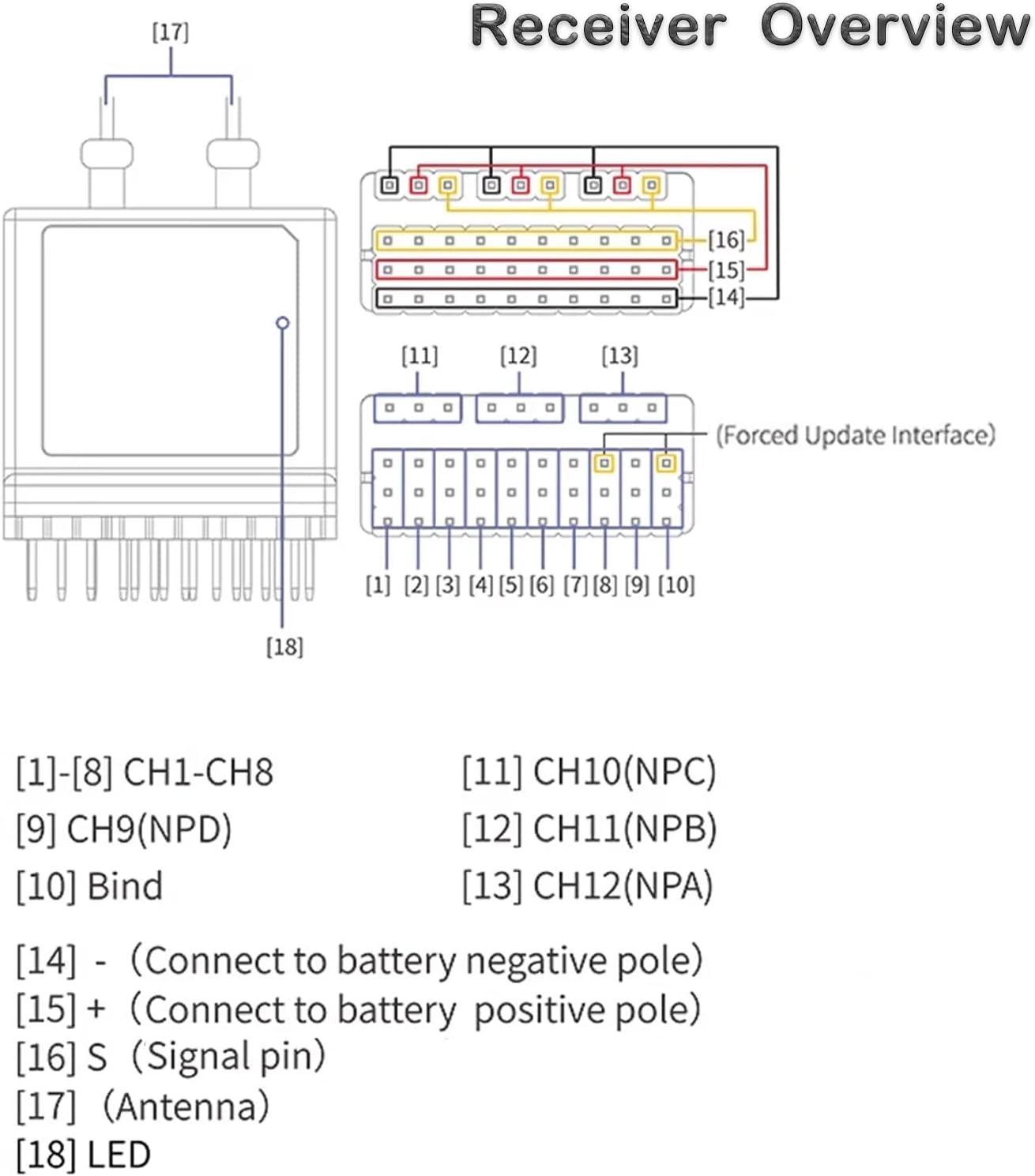
Figure 2.1: Detailed diagram of the FBr12 receiver's pinout and components.
2.1 Pinout Description
- [1]-[8] CH1-CH8: Standard PWM output channels 1 through 8.
- [9] CH9(NPD): Channel 9, typically used for specific functions or data output.
- [10] Bind: Pin used for initiating the binding process with a compatible transmitter.
- [11] CH10(NPC): Channel 10.
- [12] CH11(NPB): Channel 11.
- [13] CH12(NPA): Channel 12.
- [14] - (Connect to battery negative pole): Ground connection for power.
- [15] + (Connect to battery positive pole): Positive power input.
- [16] S (Signal pin): Signal input/output pin.
- [17] Antenna: Dual antennas for signal reception.
- [18] LED: Status indicator light.
The receiver also features a "Forced Update Interface" for firmware updates, ensuring the device remains current with the latest protocols and improvements.
3. Specifications
Below are the detailed technical specifications for the GoolRC Flysky FBr12 Receiver:
| Specification | Value |
|---|---|
| Product Model | FBr12 |
| Adaptive Transmitters | All transmitters supporting AFHDS 3 (EL18, PL18, PL18 EV, NB4 Pro, NB4+, etc.) |
| Model Type | Car, Boat, etc. |
| PWM Channels | 12 |
| Wireless Frequency | 2.4GHz ISM |
| Wireless Protocol | AFHDS 3 |
| Antenna Type | Dual antenna (length: 35cm) |
| Input Power | 3.5~9V DC |
| Data Output | PWM/PPM/i-BUS/S.BUS/i-BUS 2 |
| Waterproof Rating | PPX7 |
| Temperature Range | -10°C to +60°C |
| Humidity Range | 20~95% |
| Online Update | Yes |
| Dimensions | 32.4 x 38.3 x 14mm |
| Weight | 18g (without pin header) |
| FCC ID | 2A2UNFBR1200 |

Figure 3.1: Visual representation of the FBr12 receiver with key dimensions and specifications.
4. Setup and Installation
Proper setup and installation are crucial for the optimal performance of your FBr12 receiver. Follow these steps to get started:
4.1 Connecting the Receiver
- Power Connection: Connect the positive (+) lead from your power source (3.5V to 9V DC) to pin [15] and the negative (-) lead to pin [14] on the receiver. Ensure correct polarity to prevent damage.
- Channel Connections: Connect your servos, ESCs, or other components to the appropriate PWM channels [1]-[8] and [9]-[13] as required by your model. Refer to the "Receiver Overview" diagram (Figure 2.1) for pin assignments.
- Antenna Placement: Position the dual antennas [17] away from metal objects and other electronic components to maximize signal reception. Ensure they are extended and not coiled.
4.2 Binding Process
To establish communication between the FBr12 receiver and your AFHDS 3 compatible transmitter, you must perform a binding procedure. The exact steps may vary slightly depending on your transmitter model, but generally involve:
- Ensure both the receiver and transmitter are powered off.
- Connect a bind plug (or short the bind pins) to the [10] Bind pin on the receiver.
- Power on the receiver. The LED [18] on the receiver should indicate it is in binding mode (refer to your transmitter's manual for specific LED indications).
- Put your transmitter into binding mode (consult your transmitter's user manual for instructions).
- Once binding is successful, the receiver's LED will change to a solid light, indicating a successful connection.
- Power off both the receiver and transmitter, then remove the bind plug from the receiver.
- Power on the transmitter first, then the receiver, to confirm the connection.

Figure 4.1: Overview of the FBr12 receiver and its compatibility with various Flysky AFHDS 3 transmitters.
5. Operation
The FBr12 receiver offers versatile data output options and broad compatibility with AFHDS 3 transmitters.
5.1 Data Output Options
The receiver supports the following data output protocols:
- PWM (Pulse Width Modulation): Standard output for individual servo and ESC control.
- PPM (Pulse Position Modulation): A single wire carries all channel data, commonly used for flight controllers.
- i-BUS: Flysky's proprietary digital serial bus protocol, offering multiple channels over a single wire.
- S.BUS: Futaba's proprietary digital serial bus protocol, also offering multiple channels over a single wire.
- i-BUS 2: An enhanced version of Flysky's i-BUS protocol.
Select the appropriate output mode based on your flight controller or other connected devices. Refer to your device's manual for compatible input types.
5.2 Transmitter Compatibility
The FBr12 receiver is designed to work seamlessly with a wide range of Flysky transmitters that support the AFHDS 3 protocol. The table below provides a compatibility matrix for various Flysky transmitters and receivers. A checkmark (✓) indicates compatibility, while an 'x' indicates incompatibility or that the product is no longer in production.

Figure 5.1: Compatibility matrix for Flysky AFHDS3 transmitters and receivers, including the FBr12.
Note:
- PL18 EV and FRM302 currently do not have AFHDS3 3.0 high-frequency library firmware.
- Inr6 HS, TMR, FGr4B 2.0 high-frequency library firmware without AFHDS3.
- "x" means semi-compatible, which means that the basic channel signal output can be paired and used, including the following conditions:
- Some transmitters are matched with gyroscope receivers, barometer receivers, etc., but can only be used as ordinary receivers.
- The current 2.0 high-frequency library firmware of PL18EV and FRM302 cannot fully utilize the advanced features.
6. Maintenance
To ensure the longevity and reliable performance of your FBr12 receiver, consider the following maintenance guidelines:
- Waterproof Protection: The FBr12 has a PPX7 waterproof rating, meaning it can withstand immersion in water up to 1 meter for 30 minutes. While designed for harsh conditions, avoid prolonged submersion or exposure to corrosive liquids. After exposure to water, ensure the receiver is thoroughly dried before storage or next use.
- Temperature and Humidity: Operate and store the receiver within its specified temperature range of -10°C to +60°C and humidity range of 20% to 95%. Extreme temperatures or humidity can affect performance and lifespan.
- Cleaning: Periodically clean the receiver's exterior with a soft, dry cloth. Avoid using solvents or harsh chemicals.
- Antenna Care: Handle the antennas carefully. Avoid bending them sharply or subjecting them to excessive force, which can damage the internal wiring and affect signal quality.
7. Troubleshooting
If you encounter issues with your FBr12 receiver, consider the following common troubleshooting steps:
- No Power/LED Off:
- Check power connections to pins [14] and [15]. Ensure correct voltage (3.5V-9V) and polarity.
- Verify the power source (battery) is charged and functioning correctly.
- No Signal/Binding Failure:
- Ensure the receiver and transmitter are both in binding mode during the binding process.
- Confirm your transmitter supports the AFHDS 3 protocol and is compatible with the FBr12 (refer to Figure 5.1).
- Check the distance between the transmitter and receiver during binding; keep them close.
- Ensure no other 2.4GHz devices are causing interference during binding.
- Verify the bind plug is correctly inserted and removed at the appropriate times.
- Intermittent Signal/Range Issues:
- Check antenna placement. Ensure they are not obstructed by carbon fiber or metal parts and are extended properly.
- Inspect antennas for any physical damage.
- Ensure the transmitter's battery is fully charged.
- Avoid operating in areas with high 2.4GHz interference.
- Incorrect Channel Output:
- Verify that the correct data output mode (PWM, PPM, i-BUS, S.BUS, i-BUS 2) is selected and configured on your flight controller or connected device.
- Check the wiring from the receiver to your components.
- Firmware Update Issues:
- Ensure you are using the correct firmware update tool and follow the instructions precisely.
- Use a stable power source during updates.
For further assistance, please contact GoolRC customer support or refer to the official Flysky website for the latest firmware and detailed guides.
8. Warranty and Support
GoolRC products are manufactured to high-quality standards. For information regarding warranty coverage, returns, or technical support, please refer to the purchase platform's policies or contact GoolRC customer service directly. Keep your proof of purchase for any warranty claims.
For the latest product information, firmware updates, and additional resources, please visit the official GoolRC or Flysky websites.


