
PowMr POW-HVM10.2M
Contents
PowMr 10.2kW 48V Hybrid Solar Inverter User Manual
Model: POW-HVM10.2M
1. Introduction
This manual provides essential information for the safe and efficient operation of your PowMr 10.2kW 48V Hybrid Solar Inverter. This advanced inverter integrates a 10.2kW pure sine wave inverter, a 180A MPPT solar charge controller, and a battery charger into one compact unit. It is designed to provide reliable power for various applications, including off-grid solar systems, RVs, camping, boating, and emergency backup power for homes and offices.
Please read this manual thoroughly before installation and operation to ensure proper use and to prevent damage to the unit or injury to personnel. Keep this manual for future reference.
2. Safety Instructions
Adhering to safety precautions is paramount during installation, operation, and maintenance of the inverter. Failure to follow these instructions may result in electric shock, fire, or severe injury.
- Only qualified personnel should install or maintain this device.
- Before installation or maintenance, ensure all power sources (solar, utility, battery) are disconnected.
- Do not disassemble the inverter. There are no user-serviceable parts inside.
- Ensure proper grounding of the inverter.
- Avoid contact with live terminals.
- Install the inverter in a well-ventilated area, away from flammable materials and direct sunlight.
- Use appropriate overcurrent protection devices for all circuits.
- This inverter provides 360-degree protection against short circuits, overcurrent, overvoltage, undervoltage, overload, and overtemperature. However, proper installation and usage are still critical.

Figure 2.1: Inverter Protection Features. This diagram highlights the comprehensive safety mechanisms built into the PowMr inverter, ensuring safe and reliable operation.
3. Product Overview
The PowMr 10.2kW Hybrid Solar Inverter is a versatile power solution featuring dual PV input and dual AC output. It is designed for high efficiency and compatibility with various battery types.
3.1 Key Features
- 10.2kW Pure Sine Wave Output
- 48V DC to 220V/230V/240V AC Conversion
- Integrated 180A MPPT Solar Charge Controller
- Max PV Input Voltage: 500Vdc
- Dual PV Input and Dual AC Output for uninterrupted power
- Compatible with multiple battery types: AGM, GEL, FLD, SLD, LI (Lithium), and User-defined.
- RGB lighting modes indicating operational status (PV, Battery, Utility modes).
- Equipped with a backlit LCD display for parameter navigation and adjustment.
- Multiple protection features: short circuit, overcurrent, overvoltage, undervoltage, overload, overtemperature.
- High compatibility with household and office appliances (up to 95%).

Figure 3.1: Key Specifications of the 10.2kW Hybrid Solar Inverter. This image highlights the inverter's power capabilities and voltage ranges.
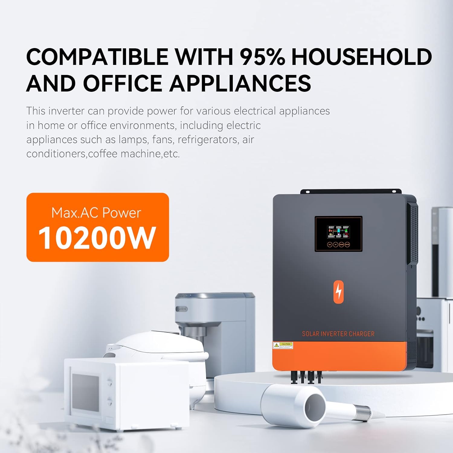
Figure 3.2: Appliance Compatibility. The inverter is designed to power a wide range of common household and office electrical appliances.
3.2 Product Components and Interface
Familiarize yourself with the various components and connection ports of the inverter.

Figure 3.3: Inverter Components and Interface. This diagram labels the LCD display, indicators, control buttons, and all input/output ports for easy identification.
- LCD display: Shows operational status and parameters.
- Status indicator: Indicates the current operational status.
- Charging indicator: Shows battery charging status.
- Fault indicator: Lights up in case of an error.
- Touch Function buttons: For navigating menus and adjusting settings.
- Power on/off switch: Main power control.
- AC input: Connection for utility grid or generator.
- Main output: Primary AC output for loads.
- Second output: Secondary AC output for loads.
- PV1 and PV2 input: Connections for solar panel arrays.
- RS-232/WIFI/Remove LCD communication port: For data communication and optional remote monitoring.
- Battery input: Connections for battery bank.
- Anti dust kit: For protection against dust ingress.
4. Setup and Installation
Proper installation is crucial for the inverter's performance and safety. Follow these steps carefully.
4.1 Site Selection
- Mount the inverter vertically on a solid surface.
- Ensure adequate clearance around the unit for proper ventilation (at least 20 cm on all sides).
- Avoid areas with high humidity, dust, or corrosive gases.
- Keep away from direct sunlight and heat sources.
4.2 Wiring Diagram
The following diagram illustrates a typical wiring setup for the PowMr hybrid solar inverter. Ensure all connections are secure and follow local electrical codes.

Figure 4.1: Typical System Wiring Diagram. This diagram shows how to connect solar panels, batteries, utility grid, and household loads to the inverter.
- Solar Panel Connection: The inverter supports dual MPPT inputs. Connect your solar panel arrays to PV1 and PV2 inputs. Recommended PV power is 10200W with a maximum open circuit voltage of 500Vdc. It is recommended to connect solar panels in series to achieve the optimal voltage range (90Vdc-450Vdc operating range).
- Battery Connection: Connect a 48V battery bank to the battery input terminals. The inverter is compatible with various battery types (AGM, GEL, FLD, SLD, LI, USER). Ensure correct polarity. Recommended cable size for battery connection is 2 AWG (25mm²) with a recommended fuse of 150A.
- AC Input Connection: Connect the utility grid or a generator to the AC input. Max AC input voltage is 300VAC with a maximum charging current of 160A. Recommended cable is 10AWG/6mm² with a recommended breaker of 63A.
- AC Output Connection: Connect your electrical loads to the main and second AC output terminals. The inverter provides 10200W AC output power at 220V/230V/240V AC. Recommended cable is 10AWG/6mm² with a recommended breaker of 63A.

Figure 4.2: Dual MPPT Input Configuration. This image demonstrates the dual solar input capability, optimizing solar energy harvesting throughout the day.
5. Operating Instructions
This section details how to operate your PowMr hybrid solar inverter, including setting up battery types, understanding charging and output modes, and interpreting RGB light indicators.
5.1 Battery Type Configuration
The inverter is compatible with various battery types. It is crucial to select the correct battery type to maximize charging efficiency and prolong battery life. Use the LCD display and function buttons to navigate to program 05 for battery type selection.

Figure 5.1: Battery Compatibility. The inverter supports a wide range of battery chemistries, allowing for flexible system design.
- AGM, GEL, FLD, SLD: Standard lead-acid battery types.
- LI (Lithium): For lithium-ion batteries. If using a lithium battery, select "User-Defined" in program 05 to configure specific charging parameters.
- USER: Allows for custom voltage settings for charging and discharging, ideal for specific battery chemistries or advanced users.
Note: If using a lithium battery, ensure the battery type "User-Defined" is selected in program 05. The lithium battery will be activated by solar energy after 3 seconds if solar energy is present.
5.2 Charging and Output Modes
The inverter offers multiple charging and output priority modes to suit different energy management strategies.

Figure 5.2: Multiple Charging and Output Modes. This visual guide explains the different operational priorities for charging batteries and supplying power to loads.
Charging Modes:
- C50 Solar First: Solar energy charges the battery as the primary source. Utility power charges only when solar is unavailable.
- SNU Solar and Utility (default): Solar energy and utility power charge the battery simultaneously.
- O50 Only Solar: Solar energy is the only charging source, regardless of utility availability.
Output Modes:
- USB Utility First: Utility power provides power to loads as the primary source. Solar and battery energy provide power only when utility power is not available.
- SUB Solar First (Default): Solar energy provides power to loads as the primary source. If solar energy is insufficient, utility power supplies power.
- SBU Priority: Solar energy provides power to loads first. If solar energy is insufficient, battery power supplies loads. Utility power is used only when battery voltage drops to a low-warning level or a preset setting point (program 12).
5.3 RGB Working Mode Indicators
The inverter features an RGB light system that visually indicates its current working mode.

Figure 5.3: RGB Working Mode Indicators. The inverter's RGB light provides a quick visual cue for its current operational state.
- White Light (Stationary Mode): Indicates a standby or idle state.
- Blue Light (Utility Mode): The inverter is primarily drawing power from the utility grid.
- Purple Light (PV Mode): The inverter is primarily drawing power from the solar PV array.
- Red Light (Battery Mode): The inverter is primarily drawing power from the battery bank.
5.4 Remote Monitoring (Optional)
The inverter supports remote monitoring and control via the "SMARTESS" app. A WiFi module and GPRS data module need to be purchased separately for this functionality.

Figure 5.4: Remote Monitoring via SMARTESS App. This image illustrates the optional remote monitoring capability, allowing users to manage the inverter from their smartphone.
6. Maintenance
Regular maintenance ensures the longevity and optimal performance of your PowMr inverter.
- Cleaning: Periodically clean the exterior of the inverter with a dry, soft cloth. Ensure ventilation openings are free from dust and debris. The inverter features a demountable insect screen for easier cleaning.
- Connections: Annually check all electrical connections for tightness and signs of corrosion. Loose connections can cause overheating and damage.
- Environment: Ensure the installation environment remains within the recommended temperature and humidity ranges.
- Battery Health: Monitor battery voltage and health regularly, especially if using lead-acid batteries.
7. Troubleshooting
This section provides solutions to common issues you might encounter with your inverter. For problems not listed here, please contact customer support.
| Problem | Possible Cause | Solution |
|---|---|---|
| Inverter not turning on. | No battery connection, low battery voltage, power switch off. | Check battery connections and voltage. Ensure power switch is ON. Charge batteries if needed. |
| No AC output. | Overload, short circuit, low battery, fault indicator lit. | Reduce load. Check for short circuits in wiring. Check battery voltage. Refer to fault codes on LCD. |
| Battery not charging from solar. | Insufficient solar input, PV connection issue, incorrect battery settings. | Check solar panel connections and sunlight. Verify PV input voltage. Ensure correct battery type is selected in program 05. |
| Inverter making unusual noise. | Overload, fan obstruction, internal fault. | Reduce load. Check for fan obstructions. If noise persists, contact support. |
| RGB light showing unexpected color. | Inverter operating in a different mode than expected. | Refer to Section 5.3 "RGB Working Mode Indicators" to understand the current operational mode. |
If the issue persists after attempting these solutions, please contact PowMr customer support.
8. Specifications
Detailed technical specifications for the PowMr 10.2kW 48V Hybrid Solar Inverter.
| Parameter | Value |
|---|---|
| Brand | PowMr |
| Model | POW-HVM10.2M |
| Rated Power | 10200 W |
| Battery Voltage | 48 VDC |
| Max. PV Input Power | 10200 W |
| PV Operating Voltage Range | 90 VDC - 500 VDC |
| Max. PV Array Open Circuit Voltage | 500 VDC |
| Max. PV Charging Current | 180 A |
| AC Output Voltage | 220 V / 230 V / 240 V AC |
| Rated Output Current | 44.3 A |
| AC Input Voltage Range | Up to 300 VAC |
| Max. AC Charging Current | 160 A |
| Dimensions (L x W x H) | 62.6 x 47.6 x 20.2 cm |
| Weight | 16.5 kg |
| Display Type | Graphic Display |
| Recommended Use | Off-grid solar systems, RV camping, boating, home use, emergency backup power |
9. Warranty and Support
PowMr products are designed for reliability and performance. For warranty information and technical support, please refer to the official PowMr website or contact your authorized dealer.
If you require assistance, please provide your product model number (POW-HVM10.2M) and a detailed description of the issue to facilitate prompt support.
For a German instruction manual in PDF format, please contact us via Amazon.
Ask a question about this manual
Ask about setup, troubleshooting, compatibility, parts, safety, or missing instructions. Manuals+ will review the question and use this page’s manual context to help answer it.