1. Product Overview
The DROK DC-DC Buck Converter (Model 200405) is a compact power supply module designed to step down a higher DC input voltage to a lower, regulated DC output voltage. It features both USB Type-C and USB-A output ports, making it suitable for powering various electronic devices. The module incorporates a synchronous rectification scheme for wide voltage range, high current capability, and high efficiency.
Key Features:
- Wide Input Voltage Range: DC 8.2V to 32V.
- Regulated Output Voltage: 3V to 20V.
- High Output Current: Up to 4.8A.
- Multiple Output Ports: Includes USB Type-C and USB-A.
- Integrated QC Identifying Chip: Compatible with various smartphones for fast charging.
- User-Friendly Design: Equipped with DC interface and connecting terminals for easy integration.
- Protective Case: Comes with a clear protective case for enhanced durability and safety.
2. Safety Information
- Input Polarity: The input terminal does not have reverse connection protection. Ensure correct polarity (positive and negative) when connecting the input power supply. Incorrect wiring will damage the board.
- Voltage Range: Do not exceed the specified input voltage range of DC 8.2V to 32V.
- Current Limits: Do not exceed the maximum output current of 4.8A. Overloading the converter can lead to overheating and damage.
- Insulation: Ensure the module is properly insulated, especially when installed without its protective case, to prevent short circuits with other components or surfaces.
- Ventilation: Provide adequate ventilation around the module, especially during high-load operation, to dissipate heat effectively.
- Children: Keep the device out of reach of children.
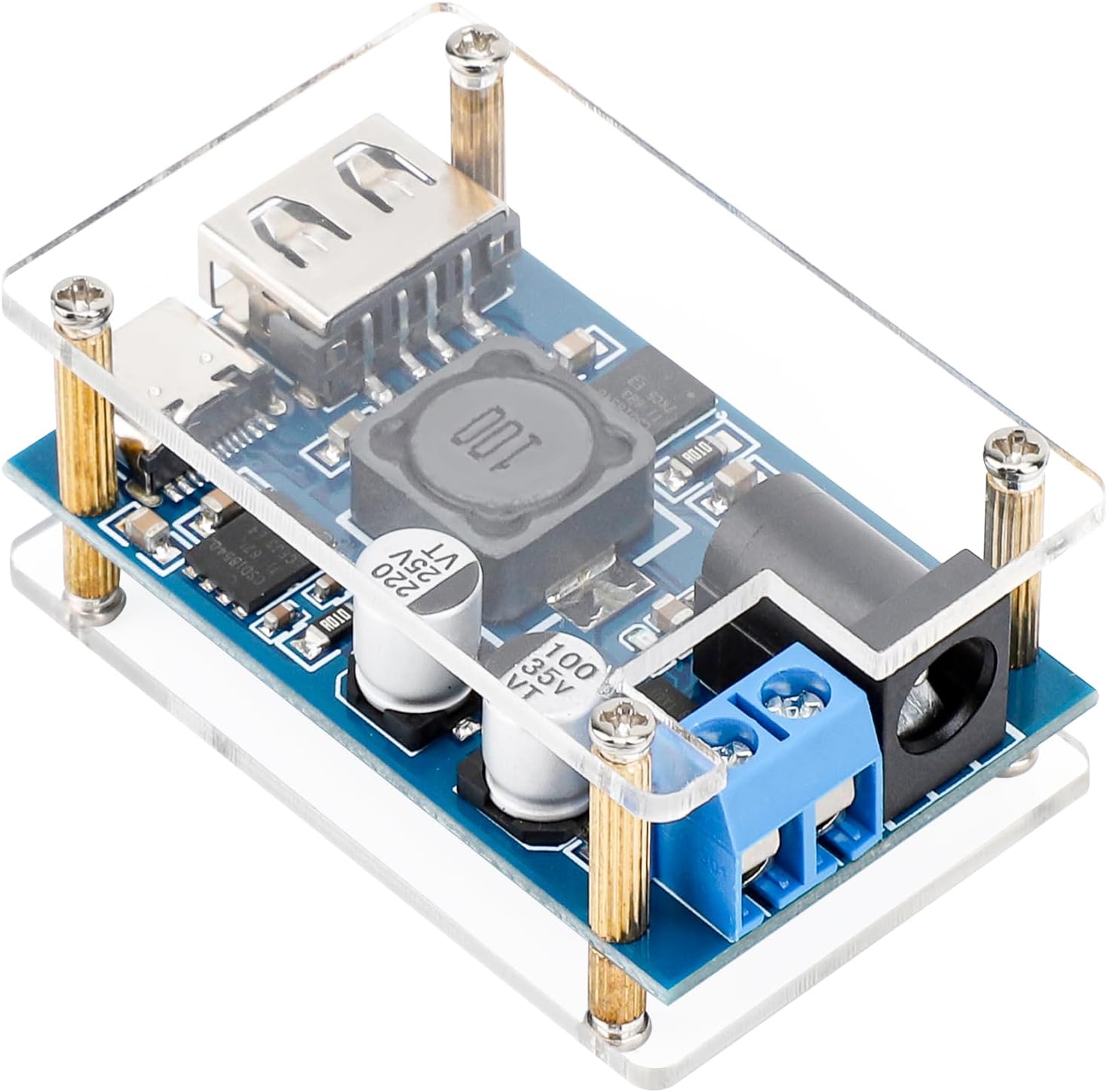
3. Product Components and Dimensions
This section details the main components and physical dimensions of the buck converter module.
Component Diagram:

Physical Dimensions:

The module's compact size allows for integration into various projects and enclosures. The protective case, shown in Figure 3.2, provides an additional layer of safety and durability.
4. Setup and Installation
Follow these steps for proper setup and installation of your DROK Buck Converter.
4.1 Assembling the Protective Case
The converter comes with a clear protective case that needs to be assembled. The package includes copper cylinder screws, double-pass screws, and roundhead screws for this purpose.
- Place the bottom acrylic plate.
- Position the buck converter module on top of the bottom plate, aligning the screw holes.
- Insert the copper cylinder screws through the module and bottom plate.
- Place the top acrylic plate, aligning it with the screws.
- Secure the assembly using the roundhead screws.

4.2 Input Power Connection
The converter accepts DC input power through two methods:
- Screw Terminals: Connect your DC power source (8.2V-32V) to the blue screw terminals. Ensure the positive (+) wire is connected to the 'Input Positive +' terminal and the negative (-) wire to the 'Input Negative -' terminal.
- Round Head Female Base: Alternatively, use a 5.5x2.1mm DC plug for input power. Ensure the plug's polarity matches the converter's (positive inside, negative outside).
Important: Double-check all connections for correct polarity before applying power. Reverse polarity will damage the module.
5. Operation
Once the input power is correctly connected, the converter is ready for use.
5.1 Output Connection
Connect your devices to the available output ports:
- USB Type-C Port: For devices compatible with USB Type-C charging.
- USB-A Port: For devices compatible with standard USB-A charging.
The converter's output voltage will be regulated within the 3V-20V range, providing appropriate power to connected devices.

5.2 Simultaneous USB Port Usage
The USB-A port and USB Type-C port can be used simultaneously. However, for optimal performance, ensure the USB-A port is connected first if both are to be used at the same time.
6. Specifications
| Parameter | Value |
|---|---|
| Model Number | 200405 |
| Input Voltage | DC 8.2V - 32V |
| Output Voltage | 3V - 20V |
| Max Output Current | 4.8A |
| Dimensions (L x W x H) | 63 x 27 x 10mm (2 x 1.06 x 0.39 inches) |
| Weight | 22g (0.986 ounces) |
| Input Interface | Screw Terminals, 5.5x2.1mm DC Jack |
| Output Interface | USB Type-C, USB-A |
7. Maintenance
To ensure the longevity and proper functioning of your DROK Buck Converter, follow these maintenance guidelines:
- Cleaning: Keep the module clean and free from dust and debris. Use a soft, dry cloth for cleaning. Avoid using liquids or abrasive cleaners.
- Storage: Store the converter in a cool, dry environment when not in use.
- Inspection: Periodically inspect the connections for any signs of wear, corrosion, or loose wiring.
- Environmental Conditions: Avoid exposing the module to extreme temperatures, high humidity, or corrosive environments.
8. Troubleshooting
If you encounter issues with your DROK Buck Converter, refer to the following troubleshooting tips:
- No Output Power:
- Verify that the input power source is connected correctly and within the specified voltage range (DC 8.2V-32V).
- Check the input polarity. Incorrect polarity will prevent operation and can damage the device.
- Ensure the input fuse is intact.
- Confirm that the output device is properly connected and functioning.
- Unstable Output Voltage or Blinking Indicator Light:
- This may indicate an overload condition. Reduce the load connected to the output ports.
- Ensure the input voltage is stable and sufficient for the load.
- Check for any short circuits on the output side.
- Overheating:
- Ensure adequate ventilation around the module.
- Reduce the load if the converter is operating near its maximum current capacity for extended periods.
- USB-A and Type-C Not Working Simultaneously:
- Ensure the USB-A port was connected first before connecting a device to the Type-C port.


