
1. Introduction
This manual provides essential information for the safe and efficient operation of your PowMr 3000W Solar Inverter. This pure sine wave inverter is designed to convert 24V DC power to 110/120V AC power, featuring a built-in 80A MPPT charge controller and compatibility with various battery types. Please read this manual thoroughly before installation and use.

Figure 1: Front view of the PowMr 3000W Solar Inverter, showcasing its compact design and integrated LCD display.
2. Safety Instructions
- Read all instructions and warnings in this manual before installation and operation.
- Installation must be performed by qualified personnel.
- Ensure proper grounding of the inverter.
- Do not disassemble the inverter. There are no user-serviceable parts inside.
- Keep the inverter away from flammable materials, moisture, and direct sunlight.
- Ensure adequate ventilation around the inverter to prevent overheating.
- Verify battery voltage and polarity before connecting to the inverter.
- Always disconnect power before performing any maintenance or wiring.
3. Product Features
The PowMr 3000W Solar Inverter offers a range of advanced features for reliable power conversion and management:
- Pure Sine Wave Inverter: Provides clean and stable AC power suitable for sensitive electronics.
- High Power Output: 3000W continuous power, converting 24V DC to 110V/120V AC.
- Integrated MPPT Charge Controller: Built-in 80A Maximum Power Point Tracking controller for efficient solar charging.
- Wide PV Input Range: Supports a maximum PV input of 4000W, 13A, with a maximum open circuit voltage of 450V.
- High Starting Voltage: Requires a starting voltage greater than 150V for PV input.
- Versatile Battery Compatibility: Compatible with 24V Lead-Acid (sealed, AGM, Gel, Flooded) and Lithium batteries.
- Multiple Charging Modes: Four selectable charging modes (PV priority, Utility Priority, Hybrid Charging, Only Solar Charging).
- Dual Output Modes: Two available output modes (Inverter and Mains).
- User-Friendly Interface: LCD display and 3 LED indicators for real-time system data and operating status.
- Advanced Protections: Includes short circuit, over voltage, under voltage, overload, and reverse polarity protection.
- Efficient Cooling: Intelligent variable speed fan for effective heat dissipation.
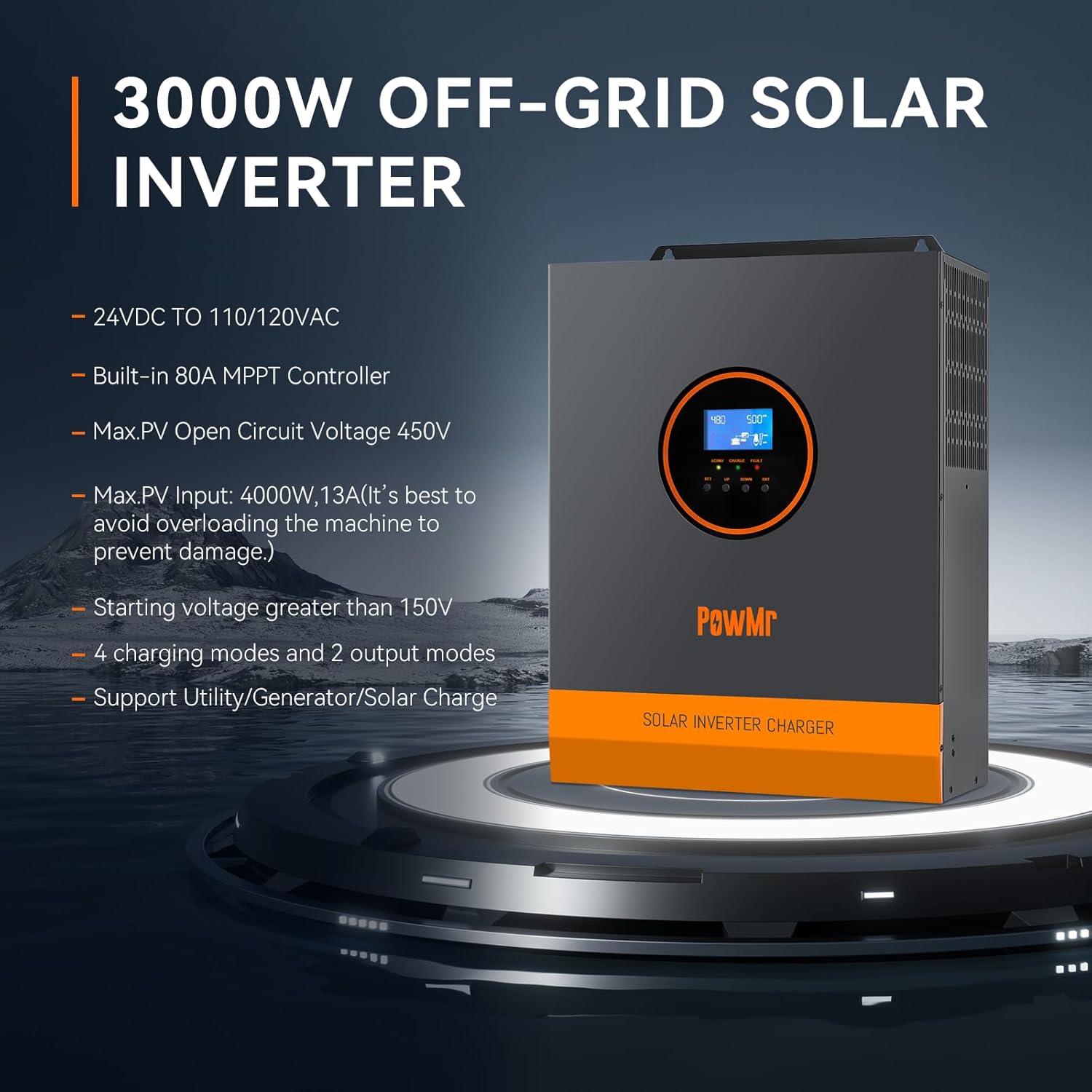
Figure 2: Overview of the PowMr 3000W Off-Grid Solar Inverter's main features, including its voltage conversion, MPPT controller, and PV input capabilities.
4. Product Overview and Components
Familiarize yourself with the various ports and indicators on your PowMr Solar Inverter:

Figure 3: Labeled diagram illustrating the various connection ports, indicators, and controls on the PowMr Solar Inverter.
| No. | Component | Description |
|---|---|---|
| 1 | AC input port | Connection for AC utility power or generator input. |
| 2 | AC output port | Connection for AC loads (e.g., household appliances). |
| 3 | CAN communication port | For communication with other CAN-enabled devices. |
| 4 | USB communication port | For data communication and monitoring. |
| 5 | RS485 communication port | For remote monitoring and control. |
| 6 | Dry contact port | Programmable relay for external control. |
| 7 | Grounding screw hole | Point for connecting the system ground. |
| 8 | Overload protector | Circuit breaker to protect against overload. |
| 9 | Battery port | Connection terminals for the battery bank. |
| 10 | Cooling fan | Dissipates heat from the inverter. |
| 11 | ON/OFF rocker switch | Main power switch for the inverter. |
| 12 | PV port | Connection terminals for solar panel input. |
| 13 | Touch the key lightly | Control buttons for navigating the LCD menu. |
| 14 | LED Indicator | Indicates operational status (e.g., AC, Charge, Fault). |
| 15 | LCD screen | Displays system parameters and settings. |
5. Installation and Setup
Proper installation is crucial for the safe and efficient operation of your inverter. Please follow these guidelines carefully.
5.1 Site Selection
- Install the inverter indoors, away from direct sunlight, rain, and moisture.
- Ensure the ambient temperature is between 0°C and 55°C (32°F and 131°F).
- Mount the inverter vertically on a sturdy wall or surface, allowing at least 20 cm (8 inches) clearance on all sides for ventilation.
- Avoid areas with excessive dust, corrosive gases, or flammable materials.
5.2 Wiring Diagram
The following diagram illustrates the recommended wiring connections for the PowMr Solar Inverter. Ensure all connections are secure and comply with local electrical codes.

Figure 4: Comprehensive wiring diagram showing connections for solar panels (in series), battery bank, AC input (from utility or generator), and AC output to various loads. Note the recommended wire gauges and voltage requirements.
- Solar Panel Connection: Connect solar panels in series to achieve a total open circuit voltage (Voc) between 150V and 450V. The starting voltage must be greater than 150V. Max PV input power is 4000W, max current 13A. Recommended PV wire: 12AWG.
- Battery Connection: Connect a 24V battery bank (Lithium or Lead-Acid) to the battery port. Recommended battery capacity: 200AH. Max Charge Current: 80A. Recommended battery wire: 2AWG. Ensure correct polarity.
- AC Input Connection: Connect AC utility power or a generator to the AC input port. AC Input Voltage: 120Vac±5%. Frequency: 50Hz/60Hz. Max AC Bypass Current: 40A. Max AC Charge Current: 40A. Recommended AC wire: 10 AWG.
- AC Output Connection: Connect your AC loads to the AC output port. AC Output Power: ≤ 3000W. Rate Voltage: 120Vac±5%. Rate Current: 27.5A.
- Grounding: Always connect the grounding screw hole to a reliable earth ground.
Important: Before making any connections, ensure the inverter's ON/OFF switch is in the OFF position and all power sources (solar, battery, utility) are disconnected.
6. Operation
6.1 Initial Power-Up
- After all wiring is complete and verified, connect the battery bank.
- Connect the solar panels.
- Connect the AC utility/generator input (if applicable).
- Turn the ON/OFF rocker switch (11) to the ON position.
- The LCD screen (15) will light up, and the inverter will perform a self-test.
6.2 LCD Display and Indicators
The LCD display provides real-time information about the system's status, including input/output voltages, battery status, and charging parameters. The three LED indicators (14) provide quick visual cues:
- AC/INV LED: Indicates AC input status or inverter operation.
- CHARGE LED: Indicates battery charging status.
- FAULT LED: Indicates a system fault or error.
6.3 Setting Parameters
Use the touch keys (13) (SET, UP, DOWN, ESC) to navigate the LCD menu and adjust various operating parameters, such as battery type, charging current, and output priority. Refer to the detailed parameter settings section in the full manual for specific instructions.
6.4 Charging Modes
The inverter offers four distinct charging modes to optimize power management based on your needs:

Figure 5: Visual representation of the four charging modes (Solar Charging, Electricity Utility Priority, Solar Priority, Hybrid Charging) and three load output working modes (PV Priority, Utility Priority, Inverter Mode).
- Solar Charging: Prioritizes solar power for charging the battery. Utility power is used only if solar power is insufficient.
- Electricity Utility Priority: Prioritizes utility power for charging the battery and powering loads. Solar power is used as a supplementary source.
- Solar Priority: Prioritizes solar power for both charging and powering loads. Utility power is used only when solar power is unavailable or insufficient.
- Hybrid Charging: Combines solar and utility power for charging, optimizing efficiency and ensuring continuous power.
6.5 Load Output Working Modes
The inverter also supports three load output working modes:
- PV Priority: Loads are primarily powered by solar energy. If solar is insufficient, battery or utility power is used.
- Utility Priority: Loads are primarily powered by utility grid. If utility fails, inverter switches to battery/solar.
- Inverter Mode: Loads are powered by the inverter from the battery, which is charged by solar or utility.
6.6 Battery Compatibility
The PowMr inverter is designed to work with a wide range of 24V battery types:
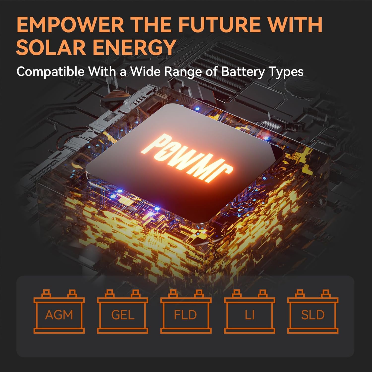
Figure 6: Visual representation of the various battery types compatible with the PowMr Solar Inverter, including AGM, Gel, Flooded (FLD), Lithium (LI), and Sealed Lead-Acid (SLD).
- Lead-Acid Batteries:
- Sealed Lead-Acid (SLA)
- Absorbent Glass Mat (AGM)
- Gel Cell
- Flooded (FLD)
- Lithium Batteries (LI): Ensure the battery management system (BMS) is compatible with the inverter's charging parameters.
Always select the correct battery type in the inverter's settings to ensure proper charging and prolong battery life.
7. Technical Specifications
| Parameter | Value |
|---|---|
| Brand | PowMr |
| Model Name | POW-LVM3K-24V (3K-24V-110/120VAC) |
| Rated Power | 3000W |
| Input Voltage (DC) | 24V DC |
| Output Voltage (AC) | 110V/120V AC |
| Waveform | Pure Sine Wave |
| Max. PV Input Power | 4000W |
| Max. PV Open Circuit Voltage | 450V DC |
| MPPT Range @ Operating Voltage | 150VDC ~ 425VDC (Starting voltage >150V) |
| Max. PV Input Current | 13A |
| Built-in MPPT Charge Controller | 80A |
| AC Input Voltage Range | 120Vac ± 5% |
| AC Input Frequency | 50Hz/60Hz (Auto sensing) |
| Max AC Bypass Current | 40A |
| Max AC Charge Current | 40A |
| Recommended Uses | Office, Home |
| Power Source | Solar Powered |
8. Troubleshooting
If you encounter issues with your inverter, refer to the following common problems and solutions. For more complex issues, contact customer support.
| Problem | Possible Cause | Solution |
|---|---|---|
| Inverter not turning on | Battery not connected or low voltage; ON/OFF switch off; loose connections. | Check battery connections and voltage; ensure switch is ON; tighten all terminals. |
| No AC output | Overload; short circuit; battery low; inverter fault. | Reduce load; check for short circuits; charge battery; check fault codes on LCD. |
| PV not charging battery | Insufficient solar input (low light, too few panels); PV voltage too low/high; wrong charging mode. | Check solar panel connections; ensure PV voltage >150V; select appropriate charging mode. |
| Overload protector trips | Connected load exceeds inverter capacity. | Reduce the total load connected to the inverter. |
| Fan constantly running or noisy | High internal temperature; dust accumulation. | Ensure adequate ventilation; clean fan vents regularly. |
9. Maintenance
Regular maintenance helps ensure the longevity and optimal performance of your PowMr Solar Inverter.
- Cleaning: Periodically clean the exterior of the inverter with a dry, soft cloth. Ensure ventilation openings are free from dust and debris. Do not use liquid cleaners.
- Connections: Annually check all electrical connections (battery, solar, AC input/output) for tightness and corrosion. Tighten any loose connections.
- Environment: Ensure the installation environment remains within recommended temperature and humidity ranges.
- Battery Health: Monitor battery voltage and health regularly, especially for lead-acid batteries, to ensure they are functioning correctly.
10. Warranty and Support
PowMr products are designed for reliability and performance. For warranty information, technical support, or service inquiries, please refer to the contact information provided with your purchase or visit the official PowMr website. Please have your model number (POW-LVM3K-24V) and purchase details ready when contacting support.