1. Introduction
This manual provides detailed instructions for the installation, operation, and maintenance of your Lithonia Lighting Basics Edge-lit LED Exit Sign, Model BE W G SM M6. This exit sign is designed for reliable safety and features bold green lighted letters with a mirrored acrylic panel for uniform brightness. Its durable thermoplastic housing resists impact, UV exposure, and corrosion, making it suitable for various commercial and institutional settings.
The sign offers a surface mount configuration for ceiling, wall, or end installation, including a 180° swivel and removable chevrons for directional flexibility. It is equipped with a selectable AC or emergency battery backup mode to ensure visibility during power outages.
Video Description: An overview of the Lithonia Lighting Edge-lit Exit Sign, highlighting its design, features, and mounting options. The video showcases the product's aesthetic and functional benefits in various environments.
2. Safety Information
- WARNING: Risk of electric shock. Disconnect power at the fuse or circuit breaker before installation or servicing.
- WARNING: Risk of fire. Keep flammable materials away from the fixture.
- Installation must be performed by a qualified electrician in accordance with the National Electrical Code and local codes.
- Ensure all connections are secure and properly insulated.
- Do not mount near gas or electric heaters.
- Do not use outdoors unless specifically rated for outdoor use. This product is UL damp location listed.
- Do not let power supply cords touch hot surfaces.
- The equipment should be mounted in locations and at heights where it will not readily be subjected to tampering by unauthorized personnel.
- The use of accessory equipment not recommended by the manufacturer may cause an unsafe condition.
- Do not use this equipment for other than its intended use.
3. Package Contents
Verify that all components are present before beginning installation:
- Edge-lit LED Exit Sign Unit
- Mounting Hardware
- Recess J-Box (for recessed mounting)
- Trim Plate (for recessed mounting)
- Removable Chevrons
4. Specifications
| Feature | Detail |
|---|---|
| Product Dimensions | 12.13 x 1.82 x 0.4 inches |
| Item Model Number | BE W G SM M6 |
| Manufacturer | Acuity Brands Lighting |
| Brand | Lithonia Lighting |
| Size | 1-Pack | Green Letters |
| Color | White with Green Letters |
| Material | Polycarbonate |
| Mounting Type | Surface Mount (Ceiling, Wall, End) |
| Item Weight | 2.4 Pounds |
| Light Type | LED |
| Orientation | Portrait |
| Pre-printed | Exit |
| Recommended Uses | Emergency Exit |
| Voltage | 120-277V MVOLT |
| Battery | NiCad (90-minute backup) |
| Certifications | UL damp location listed, UL94V-0 flame-rated |
5. Installation
Before beginning installation, ensure power is disconnected at the circuit breaker. Follow all local and national electrical codes. Refer to the installation video for visual guidance.
Video Description: A detailed installation guide for the Lithonia Lighting Edge-lit Exit Sign, demonstrating both recessed and surface mounting procedures.
5.1. Recessed Ceiling Mounting
- Prepare Mounting Location: Position recessed kits and bar hangers between joists. Hammer in temporary 'nail in' tabs on the hanger to hold it in place, then secure permanently with the included recess bracket screws for metal joists or wood. Adjust the recessed kit vertically to the desired position and tighten all screws.
- Access Wiring Compartment: Use a screwdriver to gently open the front cover of the unit. Remove the top hole plug and feed the AC supply wires through the center hole. Snap the front cover back in place.
- Install J-Box: Install the recess J-Box (included with the unit) by feeding wires through the J-Box and installing with the included J-Box screws.
- Electrical Connections: Make the electrical connections to the unit inside the J-Box (refer to the wiring diagram in the full manual). Ensure a strain relief is provided by the contractor. Secure the lid of the J-Box with the J-Box to J-Box Screw (M4 x 5mm) and torque to 5.3 in-lbs / 0.6 N·m.
- Prepare for Trim Plate: Route the Status LED harness and Test Button harness through the Recess Bracket between the Trim Plate Mounting Tab and Spring Clip.
- Assemble Trim Plate: Remove the end cap with the Test Switch and Status LED using a #1 Philips Screwdriver. Remove the Test Button by unplugging the Test Button Connector, pinching the lever locks on the inside of the End Cap, and pushing the Test Button through the End Cap. Remove the Status LED from its mounting bushing by gently pushing it back through the End Cap. Route the Status LED through the larger Test Button hole. Reinstall the End Cap with the same screws, ensuring wires from the Test Button and Status LED are pulled through the Test Button hole. Install the Trim Plate Insert with Test Button and Status LED Mounts into the Trim Plate. Push the Test Button into the trim plate front side until lock ramps snap in place and reconnect the connector. Insert the Status LED Bushing into the front side of the trim plate and push the Status LED into the bushing from the backside of the trim plate. Reconnect the test button connector.
- Install Trim Plate: Install the Trim Plate with included Trim Plate Screws (M4 x 5mm) and torque to 3.5 in-lbs / 0.4 N·m. These screws are shipped inside the Universal Mount Accessory Kit located inside the J-Box.
- Insert Exit Panel: Insert the exit panel into the main body assembly gently. If a single-sided panel is desired, remove all 4 snaps using a tool that will not scratch the sign. Remove the clear film off the shiny side of the back panel and line up the back panel with the shiny side out. Apply snaps by squeezing them in place in the same orientation. If a double-sided sign is desired, add snaps without the back panel.
- Adjust Chevrons: Make sure the Chevron orientation is correct by peeling unnecessary Chevron(s) off with a finger and cleaning any residue off the surface.
5.2. Ceiling or Wall Mounting
- Access Wiring Compartment: Use a screwdriver to gently open the front cover of the unit. Remove the top hole plug and feed the AC supply wires through the center hole. Snap the front cover back in place.
- Mount the Unit: Install the unit per configuration 1 with a Crossbar, or configuration 2 without a Crossbar. Canopy Crossbar Screws (M4 x 20mm) should be torqued to 7.0 in-lbs / 0.8 N·m. Canopy J-Box Screws (6-32 X 1/2") should be torqued to 7.0 in-lbs / 0.8 N·m. Hardware is included in the Surface Mount Accessory Pack Kit. Remember to tuck wires neatly into place.
- Insert Exit Panel: Insert the exit panel into the main body assembly gently. If a single-sided panel is desired, remove all 4 snaps using a tool that will not scratch the sign. Remove the clear film off the shiny side of the back panel and line up the back panel with the shiny side out. Apply snaps by squeezing them in place in the same orientation. If a double-sided sign is desired, add snaps without the back panel.
- Adjust Chevrons: Make sure the Chevron orientation is correct by peeling unnecessary Chevron(s) off with a finger and cleaning any residue off the surface.
- Panel Rotation: The unit can be installed on any surface. The panel can rotate along its axis of rotation to accommodate different surface angles.
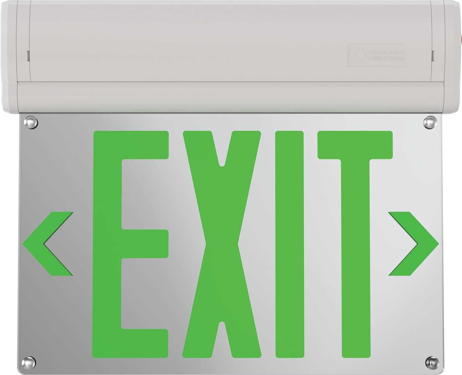
Image Description: A clear front view of the Lithonia Lighting Basics Edge-lit LED Exit Sign, displaying bright green 'EXIT' letters with directional arrows on a mirrored panel.

Image Description: A detailed diagram highlighting key features of the BE Exit Sign, such as surface mount options, AC/Battery Back-up (EL) switch, double-sided standard, and high-end aesthetic with an 8mm thick mirrored acrylic light guide plate.

Image Description: A diagram illustrating the physical dimensions of the exit sign, showing a height of 10.53 inches and a length of 12.13 inches.
6. Operating Instructions
- Initial Power-Up: After installation and restoring power, the exit sign will illuminate. The battery will begin charging automatically. Allow at least 24 hours for the battery to fully charge before performing a test.
- Battery Test: Press and hold the 'Test' button located on the side of the unit. The sign should remain illuminated, indicating the battery backup is functional. Release the button to return to AC power.
- Monthly Test: Conduct a 30-second test monthly by pressing the 'Test' button.
- Annual Test: Conduct a 90-minute test annually. Disconnect AC power to the unit for 90 minutes. The sign should remain illuminated for the entire duration. Reconnect AC power after the test.
7. Maintenance
- Cleaning: Clean the sign's surface and acrylic panel with a soft, damp cloth. Do not use abrasive cleaners or solvents.
- Battery Replacement: The NiCad battery is designed for long life. If the unit fails the monthly or annual test, the battery may need replacement. Contact a qualified technician for battery replacement.
- Inspection: Periodically inspect the unit for any physical damage, loose connections, or signs of wear.
8. Troubleshooting
| Problem | Possible Cause | Solution |
|---|---|---|
| Sign does not illuminate (AC power) | No AC power, loose wiring, faulty LED driver. | Check circuit breaker. Verify all wiring connections. Contact a qualified electrician. |
| Sign does not illuminate during battery test | Battery not charged, faulty battery, faulty charging circuit. | Allow 24 hours for initial charge. If problem persists, battery may need replacement. Contact a qualified technician. |
| Sign flickers or dims | Unstable power supply, loose connection, aging components. | Check power supply stability. Verify wiring. Contact a qualified electrician or technician. |
9. Warranty and Support
This Lithonia Lighting Basics Edge-lit LED Exit Sign is covered by a 2-year limited warranty from the date of purchase. This warranty covers defects in materials and workmanship under normal use.
For warranty claims, technical support, or further assistance, please contact Lithonia Lighting customer service. Keep your purchase receipt as proof of purchase.
Manufacturer: Acuity Brands Lighting


