1. Introduction
This manual provides detailed instructions for the safe and effective use of your DALY LifePO4 20S 60V 100A Battery Management System (BMS) protection board. Please read this manual thoroughly before installation and operation to ensure proper functionality and safety.
Safety Precautions
- Always wear appropriate personal protective equipment (PPE) when handling batteries and electrical components.
- Ensure all connections are correct and secure before applying power. Incorrect wiring can cause damage to the BMS, battery pack, or connected devices.
- Do not short-circuit the battery terminals or the BMS output.
- Keep the BMS away from water, moisture, and extreme temperatures.
- If you are unsure about any step, consult a qualified professional.
2. Product Overview
The DALY LifePO4 20S 60V 100A BMS is a robust battery management system designed to protect LifePO4 battery packs with 20 series cells, operating at 60V nominal voltage with a 100A current rating. It features comprehensive protection functions and a durable design.

Key Features:
- Multi-Function Protection: Includes over-charging, over-discharging, over-current, temperature, and short-circuit protection.
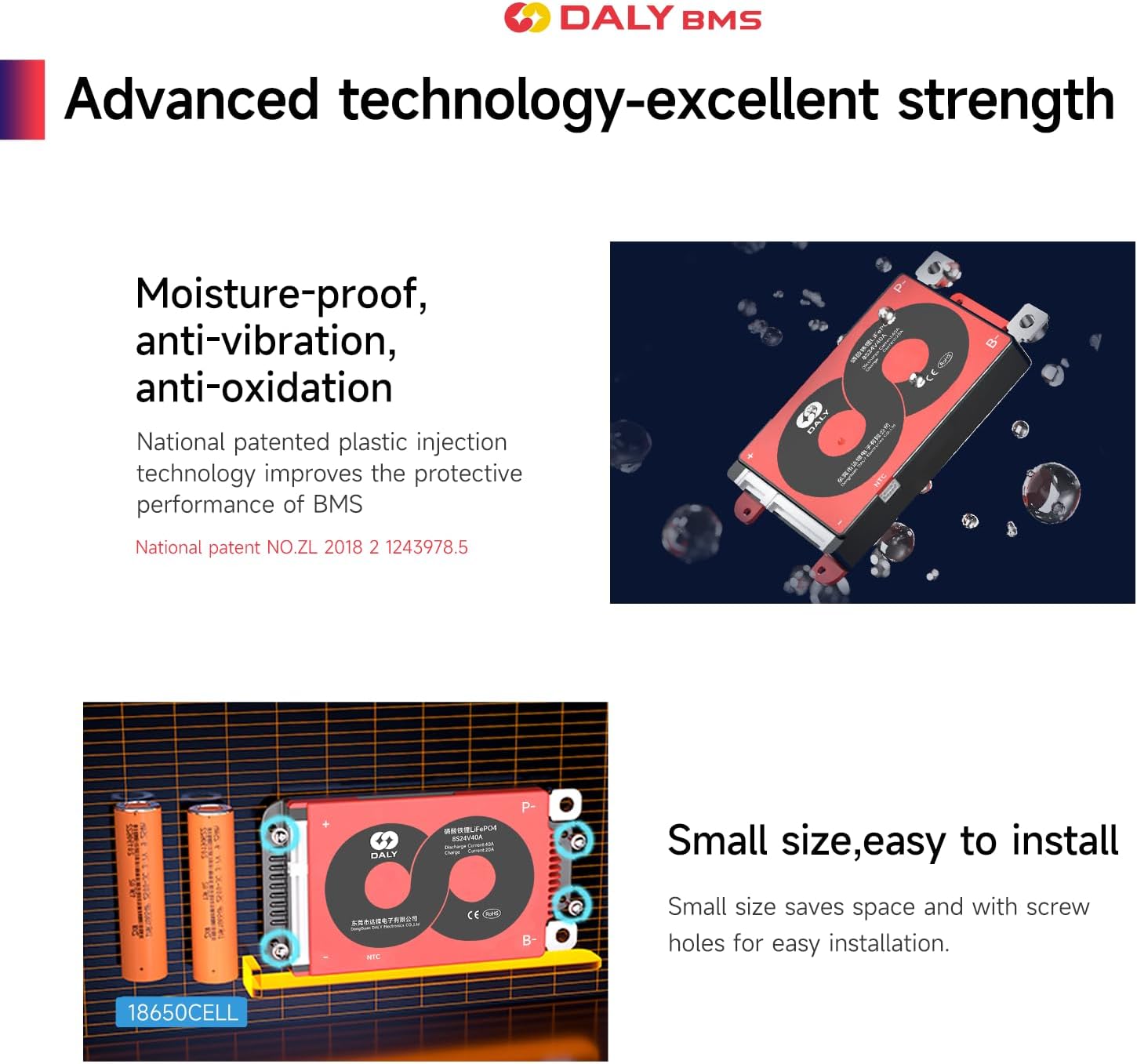
- Durable Construction: Utilizes an injection molding sealing process for dustproof, shockproof, waterproof, and anti-accumulation properties.
- Enhanced Performance: Features a smaller size, pre-charging function, 100mA passive balancing current, low temperature rise, and consistent charge/discharge current.
- Easy Installation: Designed for straightforward plug-and-play connection to the battery pack.
3. Specifications
The following table details the technical specifications of the DALY LifePO4 20S 60V 100A BMS.

| Parameter | Value |
|---|---|
| Product Type | LifePO4 20S 100A (Common Port with Balance) |
| Nominal Voltage | 60V |
| Discharge Current | 100A |
| Overdischarge Current | 266 ± 20A |
| Charging Current | 100A |
| Overcharge Current | 106 ± 20A |
| Overcharge Voltage | 3.75V ± 0.05V per cell |
| Overdischarge Voltage | 2.2V ± 0.05V per cell |
| Charge Voltage | 73V (for 20S pack) |
| Model | R24K (11-24S) |
| Dimensions (L x W x H) | 123 x 65 x 14 mm (4.84 x 2.56 x 0.55 inches) |
| Output Wire | 7AWG/100mm |
| Balance Cable | 24AWG/450mm |
| Weight | 260 ± 60g (7.7 ounces) |
4. Basic Protection Functions
The DALY BMS integrates multiple protection mechanisms to ensure the safety and longevity of your battery pack.
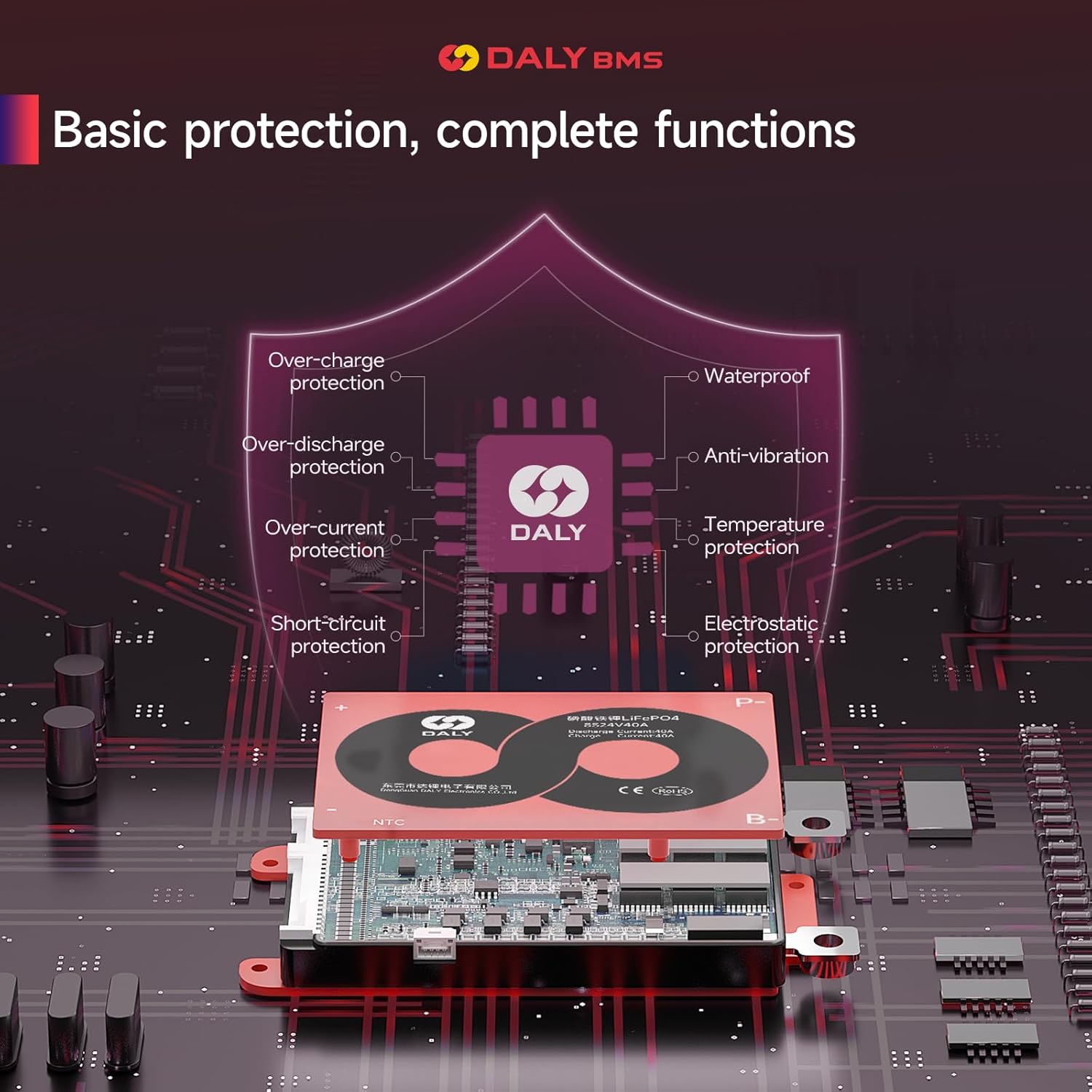
- Over-charge Protection: Prevents cells from being charged beyond their safe voltage limit.
- Over-discharge Protection: Stops discharge when cells reach their minimum safe voltage, preventing damage.
- Over-current Protection: Disconnects the load if the discharge current exceeds a safe threshold.
- Short-circuit Protection: Immediately cuts off power in case of a short circuit.
- Temperature Protection: Monitors battery temperature and prevents operation outside safe temperature ranges.
- Waterproof, Anti-vibration, Anti-accumulation: The injection molding sealing process provides robust environmental protection.
5. Setup and Wiring
Proper wiring is crucial for the safe and correct operation of the BMS. The following steps outline the installation process. Refer to the wiring diagram for visual guidance.

Wiring Steps:
- Step 1: Solder the Sampling Cables. The first cable in black from the sampling cable set connects to the negative terminal of the battery pack (B-). The second cable (red) connects to the positive terminal of the first string of batteries. The third cable (red) connects to the positive terminal of the second string of batteries, and so on, until all balance cables are connected to their respective positive terminals of each cell group.
- Step 2: Check the Cables. After connecting the balance cables, measure the voltage between two adjacent cables starting from the header. Ensure there are no wrong connections or missing connections. The voltage difference between adjacent balance wires should be approximately the nominal voltage of a single cell group.
- Step 3: Connect Output Wires and Activate. Connect the B- wire of the BMS to the total negative terminal of the battery pack. Then, plug the sampling cable to the BMS. After activating the BMS, ensure that the voltage (battery voltage) between B+ & B- and the voltage between P+ & P- are consistent. P+ and P- are the main charge/discharge terminals.
The BMS is designed for easy installation, allowing for effortless electrical connection between the battery pack and the BMS.
6. Operating Instructions
Once the DALY BMS is correctly installed and wired, it will automatically manage the battery pack's charging and discharging processes, providing continuous protection.
General Operation:
- The BMS continuously monitors cell voltages, currents, and temperatures.
- During charging, it ensures no cell is overcharged and performs passive balancing to equalize cell voltages.
- During discharging, it prevents over-discharge and over-current conditions.
- In case of a protection event (e.g., over-voltage, under-voltage, over-current), the BMS will temporarily disconnect the battery from the load or charger to prevent damage. Normal operation resumes once the condition is resolved.
Suitable Applications:
This BMS is suitable for various applications requiring LifePO4 battery packs, including:
- Electric bicycles
- Electric two-wheelers
- Electric tricycles
- Electric wheelchairs
- AGV (Automated Guided Vehicles)
- Robots
- Portable power supplies
- Battery swap systems
7. Maintenance
The DALY BMS is designed for minimal maintenance. However, periodic checks can help ensure optimal performance and longevity.
- Visual Inspection: Periodically inspect the BMS and its connections for any signs of damage, corrosion, or loose wires.
- Cleanliness: Keep the BMS clean and free from dust and debris. While it is dustproof, excessive accumulation can affect heat dissipation.
- Environmental Conditions: Ensure the BMS operates within its specified temperature and humidity ranges.
- Firmware (if applicable): Standard BMS models do not typically have communication functions for user-upgradable firmware. If you have a smart BMS model, refer to its specific instructions for firmware updates.
8. Troubleshooting
If you encounter issues with your DALY BMS, consider the following troubleshooting steps:
- No Output Voltage: Check all wiring connections, especially the main B- and P- terminals, and the balance wires. Ensure the battery pack voltage is within the operational range and not in an over-discharge state.
- BMS Not Activating: Verify that the balance cable is correctly plugged into the BMS and that the main battery connections are secure.
- Frequent Protection Triggers: This could indicate an issue with the battery pack (e.g., unbalanced cells, damaged cells) or an excessive load. Check individual cell voltages and reduce the load if necessary.
- Over-temperature Protection: Ensure the BMS has adequate ventilation and is not exposed to direct heat sources. Reduce current if the ambient temperature is high.
- Balancing Issues: If cells remain unbalanced after several charge cycles, recheck the balance wire connections for continuity and correct order.
Note: Standard DALY BMS models do not have communication functions. If you require advanced diagnostics or have a smart BMS, active balancer, parallel module, or other accessories, please contact DALY customer service for specialized support.
9. Packing List
Upon opening your DALY BMS package, please verify that all components listed below are present.

| Item | Quantity |
|---|---|
| K-BMS (DALY BMS Unit) | 1 |
| User Manual | 1 |
| B-P- Cable (Gift) | 1 |
| NTC Temperature Sensor | 1 |
| Balance Cable | 1 |
10. Warranty and Support
DALY is committed to providing high-quality products and customer satisfaction.
- Customer Service: We offer 24-hour one-on-one customer service to assist with any inquiries or issues you may have.
- Technical Support: Lifetime technical support is provided for all DALY BMS products.
- For support, please contact DALY customer service through the official channels provided at the point of purchase or on the DALY website.


