
sloHEXtted Q400
sloHEXtted Q400 4-Button Industrial Wireless Crane Remote Control Kit Instruction Manual
Model: Q400 | Brand: sloHEXtted
1. Introduction
This manual provides detailed instructions for the safe and efficient installation, operation, and maintenance of the sloHEXtted Q400 4-Button Industrial Wireless Crane Remote Control Kit. Please read this manual thoroughly before use to ensure proper functionality and to prevent potential hazards.
The sloHEXtted Q400 is designed for industrial applications such as bridge cranes, overhead cranes, chain hoists, monorails, concrete pump trucks, mobile lifting, and winch systems. It features a robust design, stable signal transmission, and an emergency stop function for enhanced safety.
2. Safety Information
WARNING: Failure to follow these safety instructions may result in serious injury or death.
- Always ensure the emergency stop button is accessible and functional.
- Do not operate the remote control if you are unfamiliar with its functions or the machinery it controls.
- Regularly inspect the transmitter and receiver for damage. Do not use if damaged.
- Ensure proper voltage supply (AC/DC 12-24V) to the receiver.
- Keep the remote control away from water and extreme temperatures unless specifically designed for such environments (IP65 rated).
- Only qualified personnel should perform installation and wiring.
- Always disconnect power to the machinery before performing any maintenance or wiring.
3. Package Contents
Verify that all components are present in the package:
- 2 x Transmitters (Remote Controls)
- 1 x Receiver
- 1 x Transmitter Button Sticker Sheet
- 1 x Transmitter Dust Sleeve
- Installation Screws and Hardware
- User Manual (this document)

Figure 3.1: Overview of the sloHEXtted Q400 kit components.
4. Specifications
| Feature | Description |
|---|---|
| Model | Q400 |
| Control Channels | 4 Buttons (Momentary System) |
| Operating Voltage | AC/DC 12-24V |
| Control Distance | Up to 100 meters (328 feet) |
| Response Time | <0.01s/m |
| Transmitter Power Source | 2 x AA Batteries (not included) |
| Material | Nylon Reinforced Fiberglass (Transmitter & Receiver Housing) |
| Protection Rating | IP65 Dust-proof and Waterproof |
| Item Weight | 2.8 pounds (total package) |
| Manufacturer Warranty | 1 Year |

Figure 4.1: Dimensions of the transmitter and receiver.
5. Setup and Installation
5.1. Transmitter Battery Installation
- Locate the battery compartment on the back of the transmitter.
- Open the battery cover.
- Insert 2 AA batteries, ensuring correct polarity.
- Close the battery cover securely.
Note: Batteries are not included and must be purchased separately.
5.2. Receiver Wiring
CAUTION: Ensure power to the crane or hoist system is completely disconnected before proceeding with wiring. Incorrect wiring can cause damage to the unit or the connected equipment.
The receiver unit has multiple wires for power input and output control. Refer to the wiring diagram on the receiver unit itself for precise connections. A general guide is provided below:
- Power Input: Connect the main power wires (AC/DC 12-24V) to the designated terminals on the receiver. Typically, one wire is for power (e.g., Wire 1 for DC power, or AC Live) and another for ground (e.g., Wire 2 for DC ground, or AC Neutral).
- Common Wire: Connect the common wire (e.g., Wire 3) to the common terminal of your hoist/crane control circuit.
- Output Wires: The remaining wires (e.g., Wires 6, 7, 8, 9) are for controlling specific functions (e.g., Up, Down, Left, Right). Connect these to the corresponding control inputs of your hoist/crane system.
- Auxiliary Wires: Some units may have auxiliary wires (e.g., Wire 4 for a light, Wire 5 for a bell/siren). Connect these as needed.
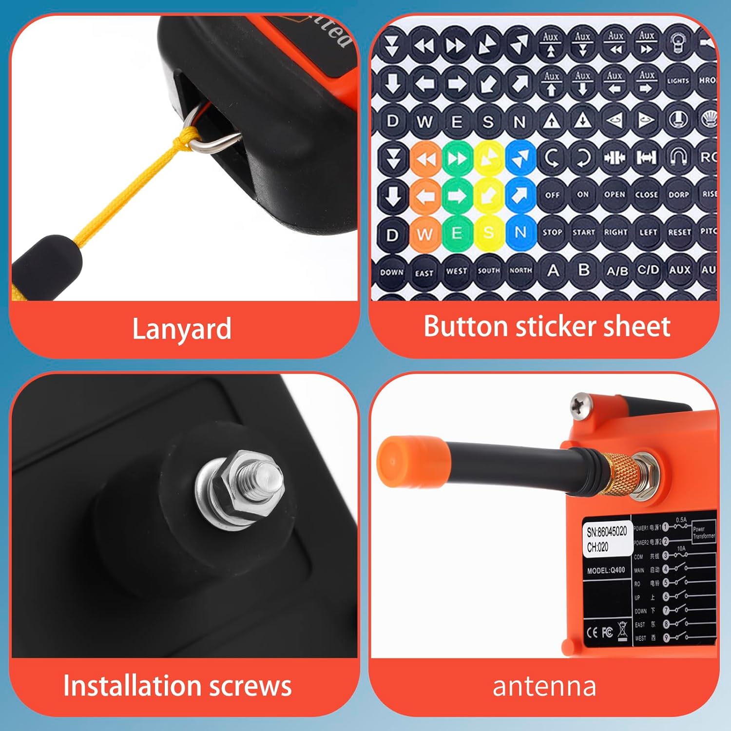
Figure 5.1: Receiver wiring diagram and connection points.
It is recommended to consult a qualified electrician for complex wiring installations, especially if your motor requires polarity reversal, which may necessitate additional relays.
5.3. Mounting the Receiver
Mount the receiver unit in a secure location, away from excessive vibration, heat, and moisture. Use the provided installation screws to firmly attach the receiver to a stable surface.

Figure 5.2: Receiver installation screws.
6. Operation
6.1. Transmitter Overview

Figure 6.1: Transmitter button layout and features.
- Emergency Stop Push Button (Red): Press to immediately stop all operations. Twist to release.
- ON/HORN Button (Green): Press to activate the system or sound the horn (if wired).
- Status LED: Indicates transmitter status (e.g., power, signal transmission).
- Silicone Buttons: Control various functions (e.g., Up, Down, Left, Right).
- Silicone Shell: Provides protection and ergonomic grip.
6.2. Initial Power-Up and Pairing
- After completing the receiver wiring, restore power to the crane/hoist system.
- Ensure the transmitter has fresh AA batteries installed.
- Press the green ON/HORN button on the transmitter. The Status LED should illuminate.
- The transmitter and receiver are typically pre-paired. If not, refer to the specific pairing instructions provided with your unit (often involves a sequence of button presses or a pairing button on the receiver).
- Test each control function (Up, Down, etc.) carefully in a safe environment before full operation.
6.3. Using the Control Buttons
The Q400 features 4 momentary buttons for controlling various functions. These buttons are designed for single-speed operation.
- Press and hold a button to activate the corresponding function.
- Release the button to stop the function.
- The included button sticker sheet can be used to label the buttons according to your specific application (e.g., Up, Down, East, West, Start, Stop, etc.).

Figure 6.2: Emergency Stop button detail.
Figure 6.3: Button sticker sheet for customization.
7. Maintenance
7.1. Cleaning
Wipe the transmitter and receiver with a soft, damp cloth. Do not use abrasive cleaners or solvents. Ensure the units are dry before use.
7.2. Battery Replacement
Replace transmitter batteries when the Status LED indicates low power or when the control range decreases. Always use new AA batteries.
7.3. Inspection
Periodically inspect the following:
- Transmitter Housing: Check for cracks, damage, or wear on the silicone shell.
- Buttons: Ensure buttons operate smoothly and return to their original position.
- Receiver Wiring: Verify all wire connections are secure and free from corrosion or damage.
- Antenna: Ensure the receiver antenna is securely attached and undamaged.

Figure 7.1: Transmitter with protective shell removed, showing internal housing.
8. Troubleshooting
| Problem | Possible Cause | Solution |
|---|---|---|
| No response from crane/hoist |
|
|
| Reduced control range |
|
|
| Intermittent operation |
|
|
9. Warranty and Support
The sloHEXtted Q400 Industrial Wireless Crane Remote Control Kit comes with a 1-Year Manufacturer Warranty from the date of purchase.
This warranty covers defects in materials and workmanship under normal use. It does not cover damage resulting from misuse, accidents, unauthorized modifications, or improper installation.
For warranty claims, technical support, or further assistance, please contact sloHEXtted customer service through the retailer where the product was purchased or visit the official sloHEXtted website.
Please retain your proof of purchase for warranty validation.
Related documentsQ400


Ask a question about this manual
Ask about setup, troubleshooting, compatibility, parts, safety, or missing instructions. Manuals+ will review the question and use this page’s manual context to help answer it.