
1. Introduction
This manual provides essential instructions for the safe and efficient operation, installation, and maintenance of your sloHEXtted Q200 Ultra Industrial Wireless Crane Remote Control system. This system is designed for controlling industrial cranes, hoists, and similar machinery, offering reliable wireless communication and robust construction. Please read this manual thoroughly before installation or operation to ensure proper usage and to prevent potential hazards.
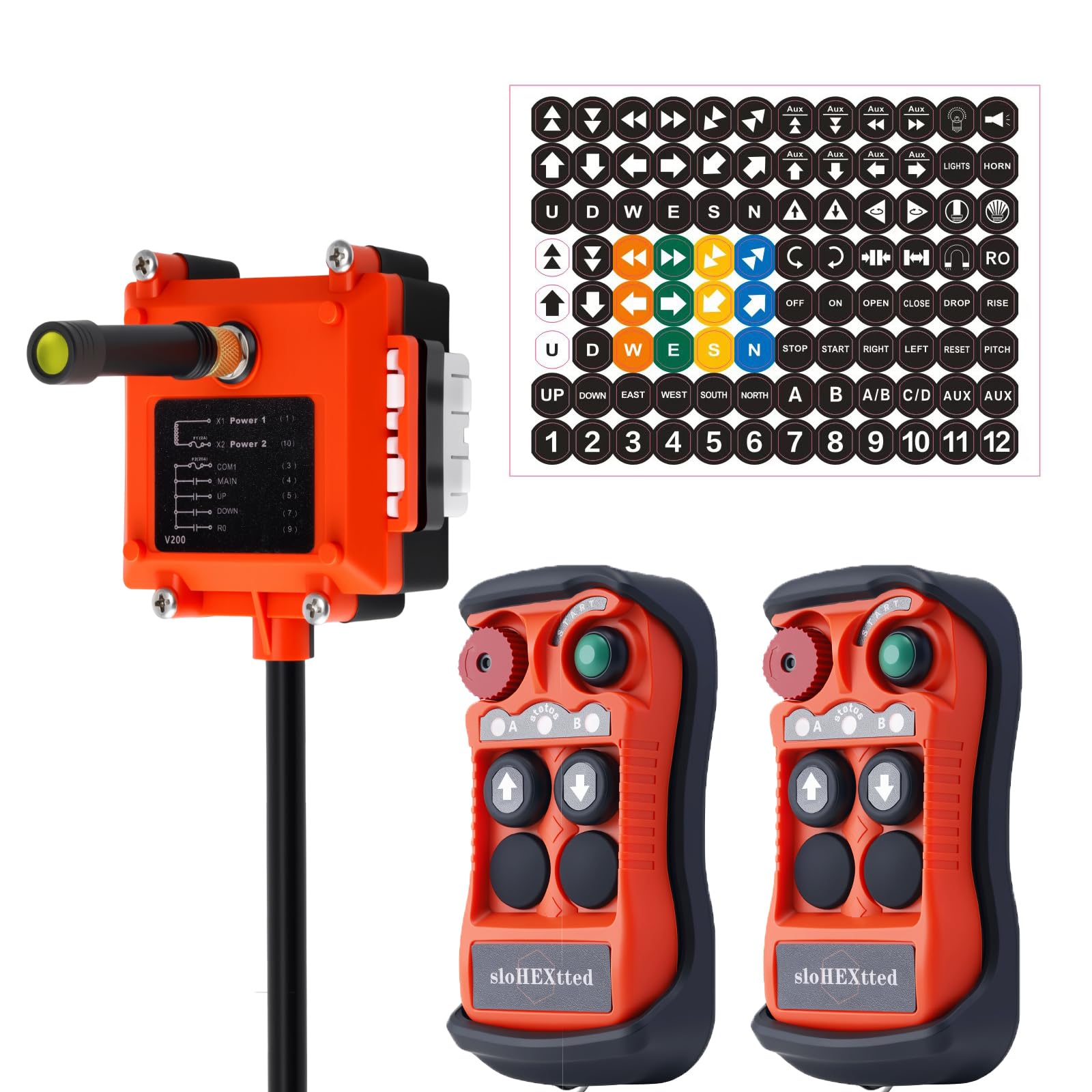
Figure 1: sloHEXtted Q200 Ultra Remote Control System
2. Safety Information
Always prioritize safety when operating industrial machinery. Failure to follow these safety guidelines may result in serious injury or equipment damage.
- Ensure all operators are trained and authorized to use the equipment and the remote control system.
- Perform a pre-operation check of the remote control and the controlled machinery before each use.
- The emergency stop button on the transmitter must be easily accessible and functional at all times. In case of any malfunction or emergency, immediately press the emergency stop button.
- Never operate the system if you suspect any damage to the transmitter, receiver, or associated wiring.
- Maintain a clear line of sight to the load and the operating area whenever possible.
- Keep the remote control dry and clean. Despite its IP65 rating, prolonged exposure to extreme conditions should be avoided.
- Do not modify the remote control system in any way. Unauthorized modifications can compromise safety and void the warranty.

Figure 2: Enhanced Safety Control Features
3. Product Overview
3.1 Components
The Q200 Ultra system typically includes:
- Transmitter (Remote Control Unit): The handheld unit with control buttons, an emergency stop button, and status indicators. It features a durable fiberglass material case and a silicone protective housing for enhanced grip and impact resistance.
- Receiver Unit: The unit installed on the machinery, which receives signals from the transmitter and controls the equipment.
- Optional Button Stickers: For customizing button functions.

Figure 3: Transmitter Components and Features
3.2 Key Features
- Stable Signal & Wide Range: Offers a control distance of up to 100 meters (328 feet) with 360-degree obstacle-free control and strong penetration. Utilizes Frequency Hopping Spread Spectrum for reliable signal in crowded environments.
- High Security & Precision: Advanced processor with multi-bit Hamming code ensures fast, secure, and precise encoding/decoding.
- Durable Construction: IP65 dustproof and waterproof rating, suitable for harsh industrial environments with oil, humidity, and dust. The transmitter and receiver casings are made from PA65 reinforced flame-retardant fiber plastic, providing resistance to pressure, corrosion, and insulation.
- Ergonomic Design: Lightweight transmitter with comfortable grip. Tactile silicone-wrapped buttons with high-performance metal contacts for durability and comfortable pressing.
- Emergency Stop: Equipped with a prominent mushroom-head emergency stop button for immediate system shutdown.
- Flexible Button Configuration: Buttons can be customized for various machine functions, supported by optional button stickers.

Figure 4: High-Efficiency Control Capabilities

Figure 5: Durable Protective Casing
3.3 Internal Technology
The Q200 Ultra incorporates advanced components for superior performance:
- SEMTECH LLCC68 RF Chip: A high-quality radio frequency chip from the USA ensures robust wireless communication.
- TI Integrated Circuit Chips: Utilizes reliable integrated circuit chips from the USA for stable operation.
- Original ALPS Switches: Imported from Japan, rated for 10 million presses, providing reactive tactile feedback for precise control and long-term industrial use.
- Sync Button: A small black sync button allows for easy and quick pairing without requiring special tools.
- Computer Configuration: The system can be connected to a computer for advanced function customization and parameter adjustment via dedicated software (Windows system required).

Figure 6: Internal Technology and Key Advantages

Figure 7: Powerful Software Customization Interface
4. Setup
4.1 Unpacking and Inspection
Carefully unpack all components. Inspect for any signs of damage during shipping. If any damage is found, do not proceed with installation and contact your supplier immediately.
4.2 Transmitter Battery Installation
The transmitter requires batteries (not included). Open the battery compartment on the back of the transmitter and insert the required batteries, ensuring correct polarity. Close the compartment securely.
4.3 Receiver Wiring
The receiver unit must be professionally installed and wired to your crane or hoist control system. Refer to the wiring diagram provided on the receiver unit and consult with a qualified electrician. Ensure the power supply matches the receiver's voltage requirements (AC/DC 12-24V for this model).
- Power Connections: Connect the appropriate power lines to X1 Power 1 and X2 Power 2 terminals.
- Common (COM): Connect the common line to the COM1 terminal.
- Control Outputs: Connect the control lines for MAIN, UP, DOWN, and other functions (e.g., R0) to their respective terminals as indicated on the receiver's wiring diagram.

Figure 8: Receiver Wiring Diagram and Product Dimensions
4.4 Pairing Instructions
The Q200 Ultra system features automatic wireless pairing. If a new transmitter or receiver is introduced, or if pairing is lost, follow these steps:
- Ensure both the transmitter and receiver are powered on.
- Locate the small black sync button on the receiver unit.
- Press and hold the sync button on the receiver for a few seconds until the status indicator on the receiver changes (e.g., flashes rapidly).
- While the receiver is in pairing mode, activate the transmitter (e.g., press the START button). The receiver will automatically search for and pair with the transmitter.
- Once paired, the status indicators on both units should show a stable connection. Test all functions before putting the equipment into service.
5. Operating Instructions
5.1 Basic Operation
- Power On: Ensure the transmitter has charged batteries and the receiver is powered.
- Start Operation: Press the green START button on the transmitter to activate the control system. The status indicators (A and B) will illuminate, showing signal strength.
- Directional Control: Use the arrow buttons (UP, DOWN, LEFT, RIGHT, etc.) to control the movement of the crane or hoist. This model features 2-speed buttons for precise control.
- Emergency Stop: In any emergency or unexpected movement, immediately press the red mushroom-head EMS button. This will cut power to the controlled machinery. To reset, twist the EMS button to release it, then press the START button again.
- Power Off: When finished, press the STOP button (if available) or the EMS button, then power off the transmitter.
5.2 Signal Strength Indicators
The transmitter features status indicators (A and B) that provide visual feedback on signal strength. Monitor these indicators during operation to ensure a stable connection. A weak or intermittent signal may indicate interference or being out of range.
6. Maintenance
6.1 Cleaning
Regularly clean the transmitter and receiver units. Use a soft, damp cloth. Do not use abrasive cleaners or solvents. Ensure all buttons are free from debris.
6.2 Battery Replacement
Replace the transmitter batteries when the low battery indicator illuminates or when operation becomes unreliable. Always use the recommended battery type.
6.3 Environmental Considerations
While the Q200 Ultra is rated IP65 for dust and water resistance, proper storage and care will extend its lifespan. Avoid storing the unit in direct sunlight, extreme temperatures, or highly corrosive environments.
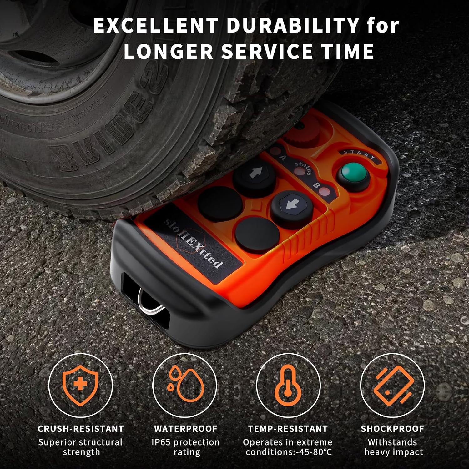
Figure 9: Durability Features
7. Troubleshooting
| Problem | Possible Cause | Solution |
|---|---|---|
| Transmitter does not power on. | Dead or incorrectly installed batteries. | Replace batteries, ensuring correct polarity. |
| No response from machinery. | 1. Emergency Stop engaged. 2. Transmitter and receiver not paired. 3. Out of range or signal interference. 4. Receiver not powered or incorrectly wired. |
1. Release EMS button and press START. 2. Re-pair transmitter and receiver (see Section 4.4). 3. Move closer to the receiver, check for obstructions. 4. Verify receiver power and wiring connections. |
| Intermittent control or signal loss. | 1. Weak batteries. 2. Environmental interference. 3. Operating at maximum range. |
1. Replace transmitter batteries. 2. Identify and mitigate sources of interference. 3. Operate within the recommended range. |
| Buttons unresponsive. | Debris under buttons or internal damage. | Clean buttons. If problem persists, contact support. |
8. Specifications
| Feature | Detail |
|---|---|
| Model | Q200 Ultra |
| Brand | sloHEXtted |
| Control Distance | Up to 100 meters (328 feet) |
| Operating Voltage | AC/DC 12-24V |
| Transmitter Style | 2 Transmitters, 1 Receiver (2T1R) |
| Enclosure Rating | IP65 (Dustproof and Waterproof) |
| Transmitter Material | PA65 Reinforced Flame-Retardant Fiber Plastic |
| Special Features | Ergonomic design, Emergency Stop, 2-speed buttons, Automatic Pairing, PC Configuration |
| Dimensions (L x W x H) | 24.13 x 20.07 x 7.62 cm (approx. 9.5 x 7.9 x 3 inches) |
| Weight | 1.07 kg (approx. 2.36 lbs) |
| Batteries Required | Yes (not included) |
| Country of Origin | China |
9. Warranty and Support
For warranty information, technical support, or service inquiries, please contact your sloHEXtted product supplier or visit the official sloHEXtted website. Please have your product model (Q200 Ultra) and ASIN (B0CZNQ429Q) available when contacting support.
Spare parts availability and software update guarantees are subject to manufacturer policies and may not be available for all components or for an indefinite period.
