GuliTech GM-MAS830B
Digital Multimeter User Manual
Model: MAS830B, MAS830L, MAS838 Series
Brand: GuliTech
1. Introduction
This user manual provides essential information for the safe and effective operation of your GuliTech MAS830 Series Digital Multimeter. This instrument is designed for measuring AC/DC voltage, DC current, resistance, and performing diode and continuity tests. Please read this manual thoroughly before use and retain it for future reference.

Figure 1: GuliTech MAS830B Digital Multimeter
2. Safety Information
Always observe the following safety precautions to prevent electric shock or personal injury, and to avoid damage to the meter or to the equipment under test.
- Do not apply voltage or current to the meter that exceeds the specified maximum.
- Use extreme caution when working with voltages above 30V AC RMS, 42V peak, or 60V DC. Such voltages pose a shock hazard.
- Always disconnect the test leads from the circuit before changing functions or ranges.
- Ensure the correct function and range are selected for the measurement.
- Inspect the test leads for damaged insulation or exposed metal before use. Replace if damaged.
- Do not operate the meter if it appears damaged or if it is not operating properly.
- Do not operate the meter in explosive gas, vapor, or dust environments.
- Remove the test leads from the meter before opening the battery cover.
3. Product Overview
The GuliTech MAS830 series digital multimeters are compact, handheld devices designed for basic electrical measurements. Key components include:
- LCD Display: Shows measurement readings and indicators.
- Function/Range Switch: Rotary switch to select desired measurement type and range.
- Input Jacks: Terminals for connecting test leads (COM, VΩmA, 10A).
- HOLD Button: Freezes the current display reading.
- hFE Transistor Socket: For testing transistor gain (MAS830L and MAS838 models).
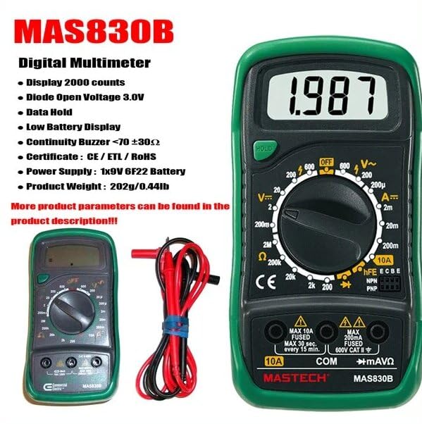
Figure 2: Key features of the MAS830B Digital Multimeter.

Figure 3: Packaging details highlighting features and specifications.
4. Setup
4.1 Battery Installation
The MAS830 series multimeters require 2 LR44 batteries (included). To install or replace batteries:
- Ensure the multimeter is turned off and test leads are disconnected.
- Locate the battery compartment on the back of the unit.
- Use a screwdriver to open the battery cover.
- Insert the batteries, observing correct polarity (+ and -).
- Replace the battery cover and secure it with the screw.
A low battery indicator will appear on the display when battery replacement is needed.
5. Operating Instructions
This section details how to perform various measurements with your digital multimeter. Always ensure the correct function and range are selected before connecting the test leads to the circuit.
5.1 AC/DC Voltage Measurement
- Set the rotary switch to the desired ACV (V~) or DCV (V-) range.
- Insert the black test lead into the "COM" jack and the red test lead into the "VΩmA" jack.
- Connect the test probes across the component or circuit to be measured.
- Read the voltage value on the LCD display.
5.2 DC Current Measurement
- Set the rotary switch to the desired DCA (A-) range.
- For currents up to 200mA, insert the red test lead into the "VΩmA" jack. For currents up to 10A, insert the red test lead into the "10A" jack. The black test lead always goes into "COM".
- Open the circuit where current is to be measured and connect the meter in series with the circuit.
- Read the current value on the LCD display.
5.3 Resistance Measurement
- Set the rotary switch to the desired Resistance (Ω) range.
- Insert the black test lead into the "COM" jack and the red test lead into the "VΩmA" jack.
- Connect the test probes across the resistor or component to be measured. Ensure the circuit is de-energized.
- Read the resistance value on the LCD display.
5.4 Diode Test
- Set the rotary switch to the Diode (♦) position.
- Insert the black test lead into the "COM" jack and the red test lead into the "VΩmA" jack.
- Connect the red probe to the anode and the black probe to the cathode of the diode.
- The display will show the forward voltage drop. Reverse the probes; the display should show "OL" (open loop) for a good diode.
5.5 Continuity Test
- Set the rotary switch to the Continuity (•))) position.
- Insert the black test lead into the "COM" jack and the red test lead into the "VΩmA" jack.
- Connect the test probes across the circuit or component.
- If the resistance is less than 70 ±30Ω, the buzzer will sound, indicating continuity.
5.6 hFE Transistor Test (MAS830L and MAS838 models only)
- Set the rotary switch to the hFE position.
- Identify if the transistor is NPN or PNP.
- Insert the transistor leads (Emitter, Base, Collector) into the corresponding holes in the hFE socket.
- The display will show the hFE (DC current gain) value of the transistor.
5.7 Data Hold Function
Press the "HOLD" button to freeze the current reading on the display. Press it again to release the hold and resume live measurements.
Video 1: Demonstration of GuliTech MAS830 Series Digital Multimeter functions, including AC/DC Voltage, DC Current, Data Hold, hFE transistor test, Diode test, and Continuity test.
6. Maintenance
6.1 Cleaning
Wipe the case with a damp cloth and mild detergent. Do not use abrasives or solvents. Ensure the meter is completely dry before use.
6.2 Battery Replacement
Refer to Section 4.1 for battery installation and replacement instructions. Replace batteries promptly when the low battery indicator appears to ensure accurate readings.
7. Troubleshooting
| Problem | Possible Cause | Solution |
|---|---|---|
| No display or dim display | Dead or low batteries | Replace batteries (2 LR44). |
| "OL" (Overload) displayed | Measurement exceeds selected range or open circuit. | Select a higher range or check circuit connection. |
| Incorrect readings | Incorrect function/range selected, poor test lead connection, or damaged leads. | Verify settings, ensure good contact, or replace test leads. |
| Buzzer not sounding during continuity test | Resistance is too high or open circuit. | Check the circuit for breaks or high resistance. |
8. Specifications
The following table outlines the general and measurement specifications for the MAS830 series digital multimeters.
| Feature | Description |
|---|---|
| Display | 2000 counts |
| Diode Open Voltage | 3.0V |
| Data Hold | Yes |
| Low Battery Display | Yes |
| Continuity Buzzer | Sounds at <70 ±30Ω |
| Power Supply | 2 LR44 batteries (included) |
| Product Dimensions | 6.3 x 3.54 x 1.97 inches |
| Item Weight | 0.5 Kilograms (1.1 Pounds) |
| Safety Rating | CAT II 600V |
8.1 Measurement Ranges and Accuracy
| Measurement Type | Range | Resolution | Accuracy |
|---|---|---|---|
| DC Voltage | 200mV/2V/20V/200V/600V | 0.1mV/1mV/10mV/0.1V/1V | ±(0.5%+3) to ±(0.8%+5) |
| AC Voltage | 200V/600V | 0.1V/1V | ±(1.2%+10) |
| DC Current | 200μA/2mA/20mA/200mA/10A | 0.1μA/1μA/10μA/0.1mA/10mA | ±(1.0%+3) to ±(3.0%+10) |
| Resistance | 200Ω/2kΩ/20kΩ/200kΩ/2MΩ | 0.1Ω/1Ω/10Ω/100Ω/1kΩ | ±(0.8%+5) to ±(1.0%+5) |

Figure 4: Detailed specifications and features of the MAS830B model.

Figure 5: Comparison of features across MAS830, MAS830B, and MAS830L models.
9. Warranty and Support
For warranty information or technical support, please refer to the contact details provided with your purchase or visit the official GuliTech website. Keep your purchase receipt as proof of purchase.
Related Documents - GM-MAS830B
 |
MASTECH Catalogue 2025: Digital Multimeters, Clamp Meters & Testing Instruments Explore the MASTECH Catalogue 2025, featuring a comprehensive range of digital multimeters, clamp meters, and electrical testing instruments. Discover detailed product specifications and selection guides for professionals and DIYers. |
 |
MASTECH® Control and Measuring Instruments Catalog 2015 Explore the comprehensive range of MASTECH® control and measuring instruments, including digital multimeters, clamp meters, insulation testers, cable testers, and more. This catalog provides detailed specifications and product information for precision electronic measurement equipment. |
 |
Manual de Instrucciones Multímetro Digital MASTER MAS830 Series Manual de usuario y especificaciones técnicas para el multímetro digital MASTER modelos MAS830, MAS830B, MAS830L, y MAS838. Incluye guías de aplicación, mantenimiento y garantía. |
 |
Mastech MAS830B Digital Multimeter Quick Start Guide A quick start guide for the Mastech MAS830B Digital Multimeter, covering its specifications, safety precautions, and basic usage for measuring voltage, current, and resistance. |
 |
MASTECH MAS830B Digital Multimeter Quick Start Guide A quick start guide for the MASTECH MAS830B Digital Multimeter, covering safety precautions, specifications, and basic measurement procedures for voltage, current, and resistance. |
 |
1997-2001 Cadillac Catera Electrical Fuses and Circuit Breakers Guide Comprehensive guide to the electrical system, including fuse block locations, power distribution blocks, ECM housing components, and relay blocks for 1997-2001 Cadillac Catera models. Features detailed diagrams and component listings. |