
1. Overview
The DIYmall RDS51150 is a high-performance digital servo designed for robotic applications requiring significant torque and precise control. Featuring a robust metal gear construction, double-shaft design, and waterproof capabilities, this servo is suitable for demanding environments. It operates within a 9-12.6V range and offers a 270-degree rotation angle, controlled via standard PWM signals.

Figure 1: DIYmall RDS51150 High-Torque Robotic Digital Servo with included accessories.
2. Package Contents
Verify that all items listed below are included in your package:
- 1 x RDS51150 Digital Metal Robotic Servo
- Assorted accessories (servo horns, mounting brackets, screws, bearings)
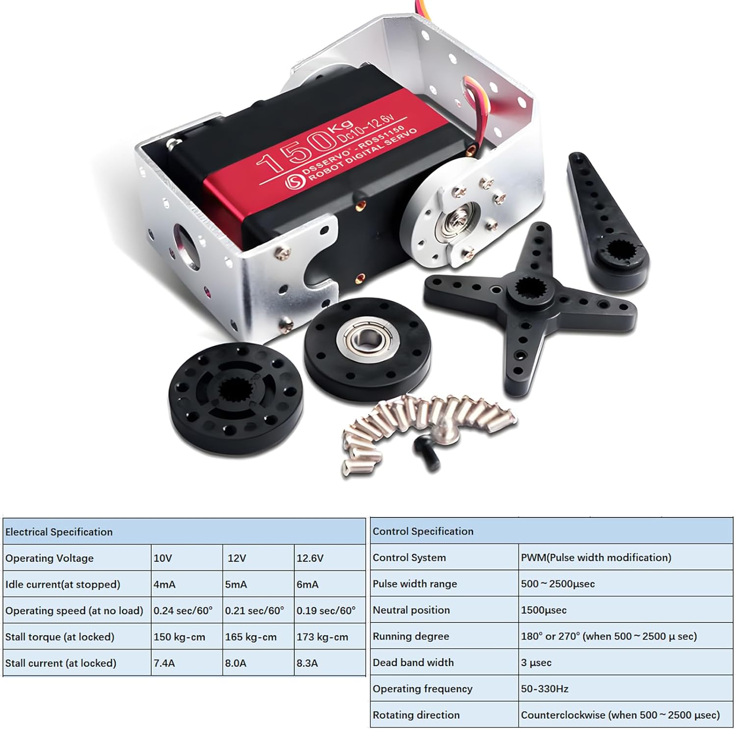
Figure 2: Contents of the RDS51150 package, including the servo and various mounting hardware.
3. Specifications
Detailed technical specifications for the RDS51150 servo are provided below:
Environmental Conditions
- Storage Temperature Range: -30℃ to 80℃
- Operating Temperature Range: -15℃ to 70℃
- Operating Voltage Range: 9V to 12.6V
Mechanical Specifications
- Size: 65 x 30 x 48 mm (2.56 x 1.18 x 1.89 inches)
- Weight: Approx. 265g (8.8 ounces)
- Gear Type: Metal Gear
- Bearing: Double Bearing
- Connector Wire: 300 ± 5mm
- Motor: 3-pole(s)

Figure 3: View of the robust metal gear system within the RDS51150 servo.
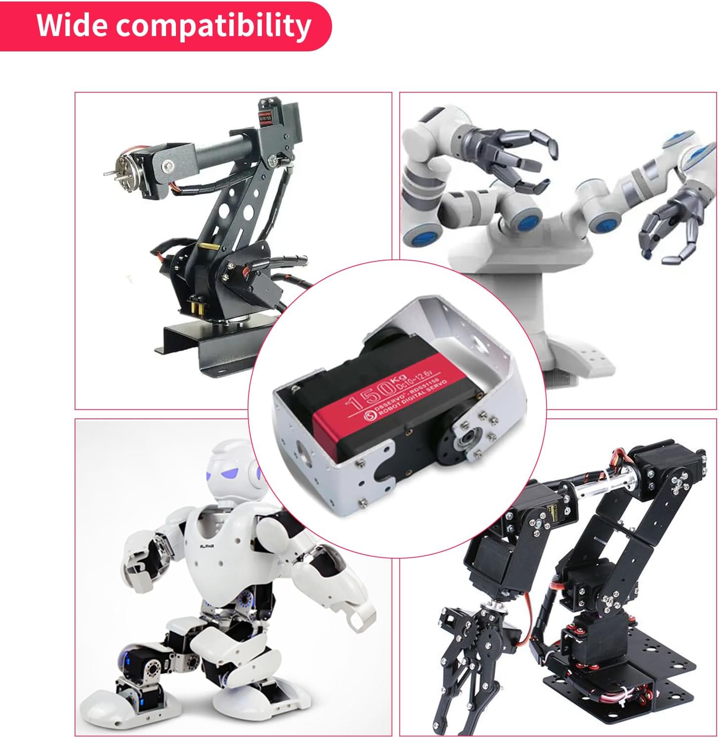
Figure 4: Detailed dimensions of the RDS51150 servo and its compatible mounting brackets.
Electrical Specifications
| Parameter | 10V | 12V | 12.6V |
|---|---|---|---|
| Idle Current (at stopped) | 4mA | 5mA | 6mA |
| Operating Speed (at no load) | 0.24 sec/60° | 0.21 sec/60° | 0.19 sec/60° |
| Stall Torque (at locked) | 150 kg.cm | 165 kg.cm | 173 kg.cm |
| Stall Current (at locked) | 7.4A | 8.0A | 8.3A |
Control Specifications
- Control System: PWM (Pulse Width Modulation)
- Pulse Width Range: 500μsec to 2500μsec
- Neutral Position: 1500μsec
- Running Degree: 270° (when 500μsec to 2500μsec)
- Dead Band Width: 3μsec
- Operating Frequency: 50-330Hz
- Rotating Direction: Counterclockwise (when 500μsec to 2500μsec)
4. Setup & Installation
Follow these steps to properly set up and install your RDS51150 servo:
- Mounting the Servo: Use the provided mounting brackets and screws to securely attach the servo to your robot or application frame. Ensure the servo is firmly fixed to prevent movement during operation. Refer to Figure 4 for dimensions and bracket configurations.
- Attaching Servo Horns: Select the appropriate servo horn for your application from the included accessories. Attach it to the servo's output shaft using the provided screw.
- Connecting the Wiring: The servo uses a standard JR-3pin connector. Connect it to your control board or receiver. The pinout is typically:
- Brown: Ground (GND)
- Red: Power (VCC, 9-12.6V)
- Orange/White: Signal (PWM)
- Power Supply: Connect a stable power supply within the 9V to 12.6V range. A 12.6V supply is recommended for optimal performance. Ensure your power supply can deliver the required stall current (up to 8.3A at 12.6V) to prevent brownouts or damage.

Figure 5: Close-up view of the servo's internal components and the JR-3pin connector.
5. Operation
The RDS51150 servo is controlled using Pulse Width Modulation (PWM) signals. The servo's position is determined by the width of the incoming pulse.
- Pulse Width Range: The servo responds to pulse widths between 500μsec and 2500μsec.
- Position Mapping (270°):
- 500μsec: Corresponds to 0° position.
- 1500μsec: Corresponds to the neutral position (approximately 135° for 270° rotation).
- 2500μsec: Corresponds to 270° position.
- Rotating Direction: The servo rotates counterclockwise when the pulse width increases from 500μsec to 2500μsec.
- Operating Frequency: The recommended operating frequency for the PWM signal is 50-330Hz.

Figure 6: Diagram illustrating the JR-3pin connector pinout and PWM signal interpretation for 180° and 270° control.
Demonstration Videos
Video 1: This video demonstrates the general movement and capabilities of the 150KG Double-Shaft servo with 270-degree rotation.
Video 2: This video illustrates the testing of the 150KG Double-Shaft servo, demonstrating its response to pulse width changes for precise control.
6. Maintenance
Proper maintenance ensures the longevity and reliable performance of your servo:
- Keep Clean: Regularly clean the exterior of the servo to prevent dust and debris accumulation, especially around moving parts and the output shaft.
- Check Connections: Periodically inspect all electrical connections for looseness or damage. Secure any loose connections.
- Avoid Overloading: Do not exceed the specified stall torque. Continuous overloading can lead to overheating and permanent damage to the motor or gears.
- Water Resistance: The servo is designed to be waterproof, offering protection against splashes and light moisture. However, it is not designed for underwater operation. Avoid submerging the servo.
- Storage: Store the servo within the recommended storage temperature range (-30℃ to 80℃) in a dry environment.
7. Troubleshooting
If you encounter issues with your RDS51150 servo, refer to the following troubleshooting tips:
- Servo Not Responding:
- Check power supply connections and ensure the voltage is within the 9V-12.6V range.
- Verify the signal wire connection to your control board.
- Confirm that the PWM signal is being generated correctly and within the 500μsec-2500μsec range.
- Ensure the power supply can provide sufficient current, especially during initial movement or under load.
- Erratic Movement or Jitter:
- Check for electrical noise in the signal line. Ensure proper grounding.
- Verify the stability of your power supply.
- Ensure the PWM signal frequency is within the 50-330Hz range and consistent.
- Check for mechanical binding or obstructions preventing smooth movement.
- Insufficient Torque:
- Ensure the operating voltage is at the higher end of the recommended range (e.g., 12.6V) for maximum torque.
- Verify that the load on the servo does not exceed its specified stall torque.
- Check for any mechanical inefficiencies in your system that might increase the required torque.
- Overheating:
- Reduce the load on the servo.
- Ensure adequate ventilation around the servo.
- Avoid continuous operation at or near stall conditions.
8. Warranty and Support
For warranty information or technical support, please contact the seller or manufacturer directly. Keep your purchase receipt as proof of purchase.
Manufacturer: DIYmall
Amazon Store: Visit DIYmall Store on Amazon
