1. Introduction
This manual provides essential information for the setup, operation, and maintenance of your LILYGO T-Beam V1.2 Meshtastic ESP32 LoRa WiFi BLE GPS TTGO Development Board. This board integrates an ESP32 microcontroller with LoRa, WiFi, Bluetooth, and GPS capabilities, making it suitable for various IoT and communication projects. Please read these instructions carefully before using the device.
2. Product Overview
2.1 Key Features
- Microcontroller: ESP32 with 4MB Flash and 8MB PSRAM
- Wireless Connectivity: Wi-Fi, Bluetooth 4.2, LoRa (915Mhz)
- GPS Module: NEO-6M for positioning and timing
- Power Management: AXP2101 PMU, supports USB and 18650 battery power
- Onboard Functions: 3 user-programmable buttons (Power, IO38, Reset)
- LoRa Transceiver: High sensitivity (-148 dBm), 300 kbps transceive rate (SX1276)
2.2 Package Contents
- LILYGO T-Beam V1.2 Development Board (915Mhz)
- LoRa Antenna
- USB Cable
- Unsoldered OLED Screen
- Pin Headers

Figure 1: LILYGO T-Beam V1.2 Development Board with included antenna and pin headers.

Figure 2: Internal component layout of the T-Beam V1.2 board, highlighting the ESP32, LoRa module, GPS module, and AXP2101 charging IC.
3. Setup
3.1 Connecting the LoRa Antenna
Carefully screw the provided LoRa antenna onto the SMA connector on the board. Ensure it is finger-tight to establish a secure connection. Do not overtighten.
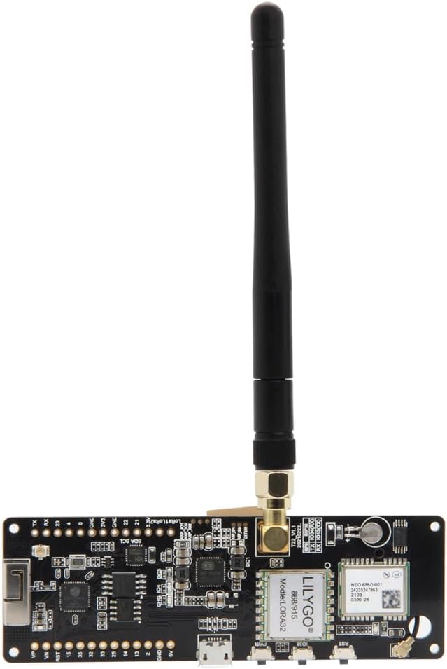
Figure 3: The LoRa antenna properly connected to the T-Beam V1.2 board.
3.2 OLED Screen Installation (Optional)
The OLED screen is provided unsoldered. If you wish to use it, you will need to solder it to the designated pins on the board (VCC, GND, SCL, SDA). Refer to the pinout diagram in Section 4.3 for correct connections.
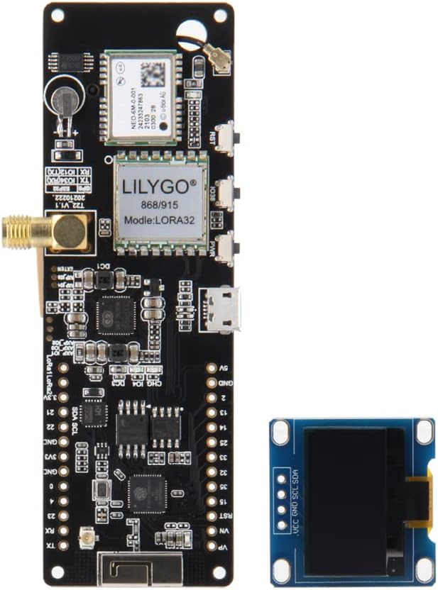
Figure 4: T-Beam V1.2 board with an OLED screen attached (requires soldering).
3.3 Power Supply
The LILYGO T-Beam V1.2 can be powered via two methods:
- USB-C Port: Connect the provided USB cable to the USB-C port on the board and to a 5V power source (e.g., computer USB port, USB wall adapter).
- 18650 Battery: Insert a 3.7V 18650 Li-ion battery into the battery holder on the back of the board. Ensure correct polarity (+/-) as indicated on the holder. The board includes a charging circuit for the 18650 battery when powered via USB.

Figure 5: The 18650 battery holder on the reverse side of the T-Beam V1.2 board.

Figure 6: Standard dimensions for an 18650 battery (18mm diameter, 65mm length).
4. Operating Instructions
4.1 Basic Operation
The board features three buttons for basic interaction:
- Power Button: Controls the main power to the board. Press and hold to turn on/off.
- IO38 Button: A general-purpose input/output button, typically used for user interaction or specific functions defined by your firmware.
- Reset Button: Restarts the ESP32 microcontroller.
4.2 LED Indicators
The T-Beam V1.2 board includes two LED indicators:
- LED1 (Charging Indicator): Illuminates when the 18650 battery is charging via USB.
- LED2 (GPS Working Indicator): Indicates activity or status of the GPS module.
4.3 Pinout Diagram
Understanding the pinout is crucial for connecting external components and programming. Refer to the diagram below for detailed pin assignments.

Figure 7: Comprehensive pinout diagram for the LILYGO T-Beam V1.2, including GPIOs, power rails, and module-specific connections.
5. Maintenance
- Cleaning: Use a dry, soft cloth to clean the board. Avoid liquids or abrasive cleaners.
- Storage: Store the board in a dry, anti-static environment when not in use.
- Battery Care: If using an 18650 battery, ensure it is of good quality and handle it with care. Do not short-circuit or expose to extreme temperatures. Remove the battery if the device will not be used for an extended period.
- Antenna: Ensure the LoRa antenna remains securely connected during operation to prevent damage to the LoRa module.
6. Troubleshooting
- Board Not Powering On:
- Check USB cable connection and power source.
- If using an 18650 battery, ensure it is charged and correctly inserted with proper polarity.
- Press and hold the Power button for a few seconds.
- No LoRa Communication:
- Verify the LoRa antenna is securely attached.
- Ensure your firmware is correctly configured for the 915Mhz frequency band.
- Check LoRa module initialization in your code.
- GPS Not Acquiring Fix:
- Ensure the device has a clear view of the sky. GPS signal acquisition can take several minutes.
- Verify GPS module initialization and data parsing in your firmware.
- Check the GPS Working Indicator LED (LED2) for activity.
- OLED Screen Not Displaying:
- Confirm the OLED screen is correctly soldered and connected to the I2C pins (SDA, SCL).
- Verify your firmware includes the correct OLED library and initialization code.
7. Specifications

Figure 8: Summary of key technical specifications for the T-Beam V1.2 board.
| Feature | Description |
|---|---|
| MCU | ESP32 (4MB Flash, 8MB PSRAM) |
| Wireless Protocol | Wi-Fi, Bluetooth 4.2 |
| LoRa Frequency | 915Mhz (SX1276 Transceiver) |
| GPS Module | NEO-6M |
| Power Management Unit (PMU) | AXP2101 |
| Power Supply Mode | USB-C (5V), 18650 Battery |
| Onboard Buttons | Power, IO38, Reset |
| Included Components | USB cable, unsoldered OLED screen |
| LoRa Antenna Connector | RG316 |
| Operating Temperature | Refer to ESP32 and module datasheets |
8. Warranty and Support
For warranty information and technical support, please refer to the official LILYGO website or contact your retailer. Keep your purchase receipt for warranty claims. Firmware updates and additional resources may be available on the manufacturer's product page or community forums.


