1. Introduction
This manual provides detailed instructions for the installation, operation, and maintenance of your ZEBRONICS ROBUST Premium Gaming Chassis. Please read this manual thoroughly before beginning assembly to ensure proper setup and optimal performance. Keep this manual for future reference.

Image 1.1: Front view of the ZEBRONICS ROBUST Gaming Chassis, showcasing its tempered glass panels and illuminated interior fans.
2. Product Features
The ZEBRONICS ROBUST chassis is designed to provide a robust and aesthetically pleasing enclosure for your gaming PC components. Key features include:
- Glass-Finish Outlook: Front and side panels are constructed from tempered glass, offering a clear view of internal components and enhancing the chassis's visual appeal.
- Motherboard Compatibility: Supports mATX (Micro-ATX) and Mini ITX motherboard form factors.
- Efficient Ventilation: Equipped with three pre-installed 120mm multicolor LED ring fans (two at the top, one at the rear) to ensure effective cooling and airflow.
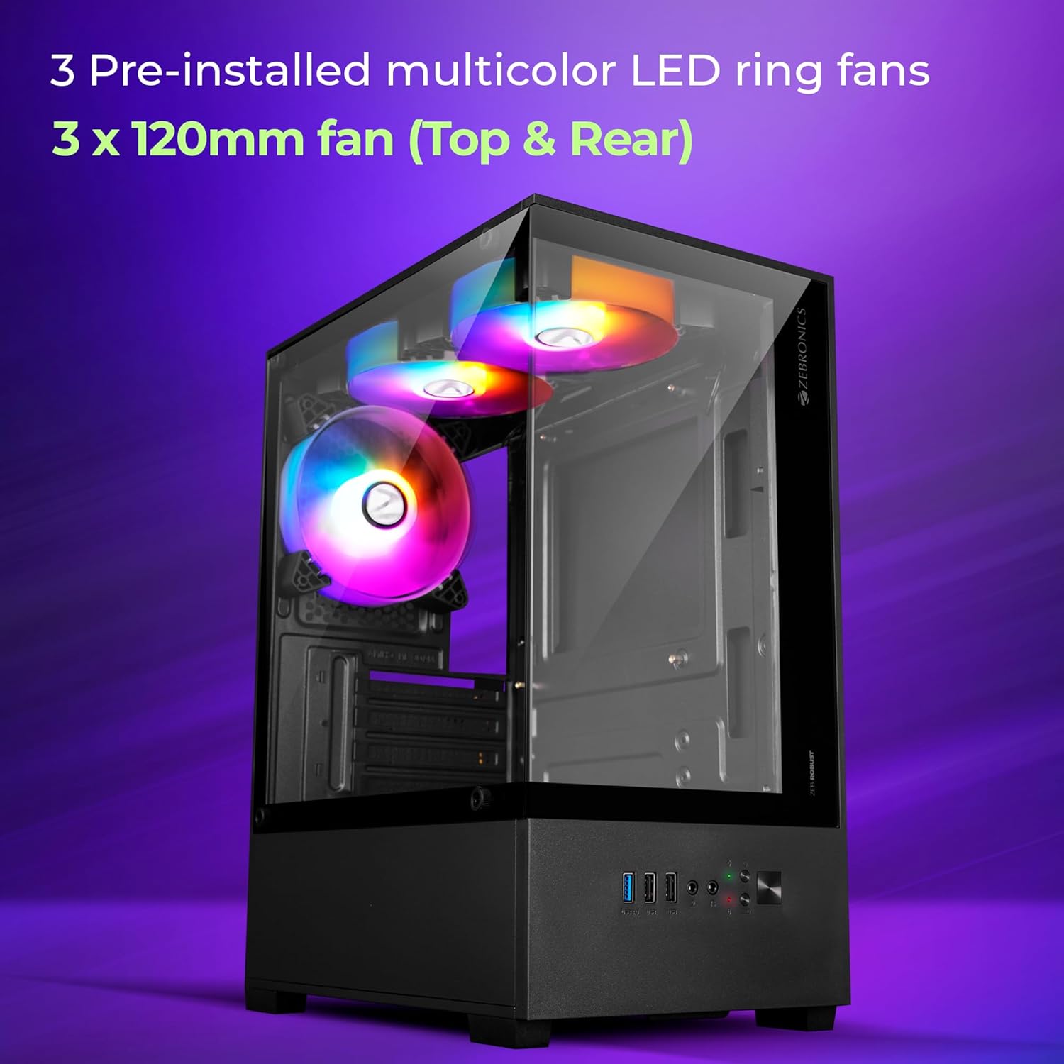
Image 2.1: Illustration highlighting the three pre-installed 120mm multicolor LED ring fans for cooling.
- Multi-Connectivity: Front panel includes one USB 3.0 port, two USB 2.0 ports, and separate microphone and headphone jacks for convenient peripheral access.
- Expansion Slots: Features four expansion slots at the rear for installing add-on cards such as graphics cards or sound cards.
- Component Accommodation: Supports VGA cards up to 255mm in length and CPU coolers up to 165mm in height. The power supply unit (PSU) is designed for bottom installation.
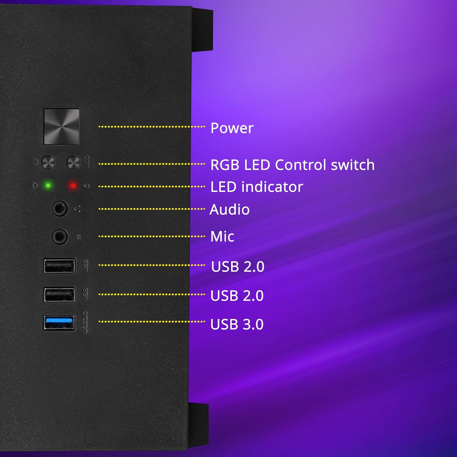
Image 2.2: Detailed view of the front panel I/O, showing the power button, RGB LED control switch, LED indicators, audio ports, and USB ports.

Image 2.3: Internal layout indicating the bottom-mounted power supply unit area and the four expansion slots for add-on cards.
- Optimized Cooling Design: Engineered for superior airflow to maintain optimal temperatures during extended use.

Image 2.4: Visual representation of the chassis's internal airflow path, designed for efficient heat dissipation.
- Dust Filtration: Includes a magnetic dust filter at the top and a detachable dust filter at the bottom to prevent dust accumulation.
- Cable Management: Designed with features to facilitate effective cable organization, reducing clutter and improving airflow.

Image 2.5: Close-up of the top magnetic dust filter, demonstrating its easy removal for cleaning.
3. Specifications
| Feature | Detail |
|---|---|
| Brand | ZEBRONICS |
| Model | Zeb-Robust |
| Case Type | Mid Tower |
| Motherboard Compatibility | mATX, Mini ITX |
| Pre-installed Fans | 3 x 120mm Multicolor LED Ring Fans (2 Top, 1 Rear) |
| Front I/O Ports | 1 x USB 3.0, 2 x USB 2.0, 1 x Mic, 1 x Headphone, Power, RGB LED Control Switch |
| Expansion Slots | 4 |
| Max VGA Card Length | 255mm |
| Max CPU Cooler Height | 165mm |
| PSU Mounting | Bottom |
| Dust Filters | Top Magnetic, Bottom Detachable |
4. Setup Guide
Follow these steps to assemble your computer components within the ZEBRONICS ROBUST chassis.
4.1. Unpacking and Panel Removal
- Carefully remove the chassis from its packaging.
- Place the chassis on a stable, flat surface.
- Locate the thumbscrews on the rear of the chassis securing the tempered glass side panel. Unscrew them and carefully remove the side panel. Set it aside in a safe place to prevent damage.
- Repeat for the other side panel if necessary for easier access.
4.2. Motherboard Installation

Image 4.1: Chassis interior indicating support for mATX and Mini ITX motherboard sizes.
- Install the I/O shield that came with your motherboard into the corresponding opening at the rear of the chassis.
- Align your mATX or Mini ITX motherboard with the pre-installed standoffs inside the chassis.
- Secure the motherboard using the appropriate screws. Do not overtighten.
4.3. Power Supply Unit (PSU) Installation
- Position your PSU in the designated bottom compartment of the chassis.
- Ensure the PSU fan is facing downwards (if the chassis has a bottom vent) or upwards, depending on your cooling preference and chassis design.
- Secure the PSU to the chassis using the screws provided with your PSU.
4.4. Storage Drive Installation
The chassis typically includes bays for 2.5-inch SSDs and 3.5-inch HDDs. Refer to your chassis's internal layout for specific mounting points.
- Locate the drive bays or mounting brackets.
- Install your SSDs or HDDs into the appropriate bays/brackets and secure them with screws.
4.5. Graphics Card (VGA) and Expansion Card Installation
- Remove the necessary expansion slot covers from the rear of the chassis.
- Insert your graphics card or other expansion cards into the corresponding PCIe slots on your motherboard.
- Secure the cards with screws to the chassis.
4.6. Connecting Front Panel Cables
Connect the front panel cables (USB, audio, power switch, reset switch, LED indicators) from the chassis to the corresponding headers on your motherboard. Refer to your motherboard manual for exact header locations.
4.7. Cable Management
Utilize the cable routing cutouts and tie-down points behind the motherboard tray to organize and secure cables. This improves airflow and aesthetics.
4.8. Reattaching Panels
Once all components are installed and cables are managed, carefully reattach the side panels and secure them with the thumbscrews.
5. Operating Instructions
5.1. Powering On/Off
- Ensure all external peripherals (monitor, keyboard, mouse) are connected.
- Connect the power cable to the PSU and a wall outlet.
- Press the power button on the front panel of the chassis to turn on your computer.
- To turn off, use the operating system's shutdown function or press and hold the power button for several seconds.
5.2. LED Fan Control
The chassis features an RGB LED Control switch on the front panel. Press this button to cycle through various lighting modes and colors for the pre-installed LED fans.
6. Maintenance
Regular maintenance helps ensure the longevity and optimal performance of your chassis and its components.
6.1. Cleaning Dust Filters
- Periodically remove the top magnetic dust filter and the bottom detachable dust filter.
- Clean the filters using compressed air, a soft brush, or by rinsing with water (ensure they are completely dry before reinstallation).
- Reattach the dust filters.
6.2. General Cleaning
- Use a soft, dry cloth to wipe down the exterior surfaces of the chassis, including the tempered glass panels.
- For stubborn smudges on glass, a mild glass cleaner applied to a cloth (not directly to the glass) can be used.
- Avoid using abrasive cleaners or solvents, as these can damage the finish.
7. Troubleshooting
This section addresses common issues you might encounter.
7.1. No Power
- Ensure the power cable is securely connected to both the PSU and the wall outlet.
- Check that the power switch on the PSU itself is in the 'ON' position.
- Verify that the front panel power switch cable is correctly connected to the motherboard header.
7.2. Fans Not Spinning / LEDs Not Working
- Check that the fan power cables are securely connected to the motherboard or a fan controller.
- Ensure the RGB LED control cable (if separate from fan power) is properly connected.
- Press the RGB LED Control switch on the front panel to cycle through modes or turn on the LEDs.
7.3. Front Panel USB/Audio Ports Not Functioning
- Verify that the USB and audio cables from the front panel are correctly connected to their respective headers on the motherboard.
- Check your operating system's device manager and audio settings to ensure drivers are installed and devices are enabled.
8. Warranty and Support
For warranty information and technical support, please refer to the documentation provided with your purchase or visit the official ZEBRONICS website. Keep your proof of purchase for warranty claims.
For further assistance, you may contact ZEBRONICS customer support through their official channels.


