1. Introduction
This manual provides essential information for the safe and efficient installation, operation, and maintenance of the CLEMSA AC 562 N sliding gate motor. Please read this manual thoroughly before installation and use, and retain it for future reference.
The CLEMSA AC 562 N is a 230 V automation motor designed for sliding gates weighing up to 500 kg. It features magnetic limit switches, a cam release system, an aluminum housing with polyester powder coating, and an ABS casing.
2. Safety Information
WARNING: Improper installation or use can lead to serious injury or property damage. Always follow safety guidelines.
- Installation must be performed by qualified personnel in accordance with local regulations and standards.
- Ensure the power supply is disconnected before performing any installation, maintenance, or repair work.
- Do not allow children to play near the gate or operate the control unit.
- Keep hands and loose clothing clear of moving parts of the gate and motor.
- Regularly inspect the gate and motor for signs of wear, damage, or malfunction.
- The gate must move smoothly and freely without obstruction for proper operation.
3. Package Contents
Verify that all components are present and undamaged before beginning installation.
- CLEMSA AC 562 N Motor Unit
- CLEMSA 62C Control Board (integrated)
- Magnetic Limit Switches
- Mounting Plate
- Release Key
- Instruction Manual (this document)
Note: A receiver card, remote controls, rack, and photocells are NOT included with this motor unit. Complete kits are available separately.
4. Specifications
| Manufacturer | CLEMSA |
| Model Number | CLEMSA AC562N |
| Power Supply | 230 V |
| Max Gate Weight | 500 kg (gate must move smoothly) |
| Power Consumption | 350 W |
| Thrust Force | 390 N |
| Gate Speed | 12 m/min |
| Product Dimensions | 50 x 20 x 40 cm |
| Weight | 9.2 kg |
| Color | Gray |

Figure 1: Front and side view of the CLEMSA AC 562 N motor with key dimensions (approx. 288mm width, 256mm height, 170mm depth, 74mm pinion height).
5. Setup and Installation
This section outlines the general steps for installing the CLEMSA AC 562 N motor. Refer to detailed diagrams for specific wiring and mounting instructions.
5.1 Component Identification
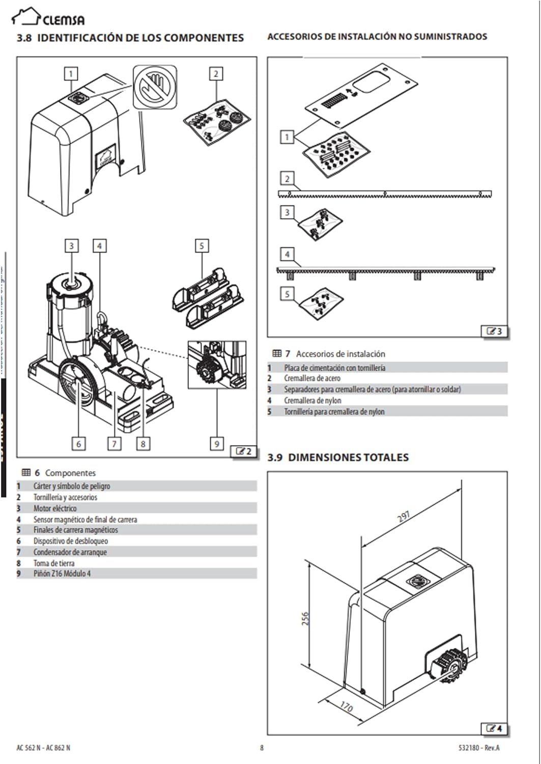
Figure 2: Diagram showing internal components of the motor and non-supplied installation accessories.
- Components:
- 1. Casing and danger symbol
- 2. Screws and accessories
- 3. Electrical terminals
- 4. Magnetic limit switch sensor
- 5. Magnetic limit switches
- 6. Unlocking device
- 7. Starting capacitor
- 8. Earth connection
- 9. Pinion Z16 Module 4
- Non-Supplied Installation Accessories:
- 1. Foundation plate with screws
- 2. Steel rack
- 3. Spacers for steel rack (for screwing or welding)
- 4. Nylon rack
- 5. Screws for nylon rack
5.2 Mounting the Motor
- Prepare a stable and level concrete foundation for the motor.
- Securely attach the mounting plate to the foundation using appropriate anchors.
- Mount the motor unit onto the mounting plate, ensuring it is level and aligned with the gate's movement path.
- Install the rack (not included) onto the gate, ensuring proper engagement with the motor's pinion. Maintain a small clearance between the rack and the pinion to prevent binding.
5.3 Electrical Connections
All electrical connections must be made by a qualified electrician.

Figure 3: The CLEMSA CLAS 62C control board, showing terminals for power, motor, accessories, and safety devices. Ensure correct wiring according to the detailed electrical diagram provided with the product.
- Connect the 230 V main power supply to the designated terminals on the CLEMSA 62C control board.
- Connect the motor wires to the motor output terminals.
- Connect the magnetic limit switches to their respective terminals.
- If using optional accessories (e.g., photocells, flashing light, external push button), connect them to the appropriate accessory terminals. Refer to the control board's specific wiring diagram for details.
- Ensure all connections are secure and properly insulated.
6. Operating Instructions
The CLEMSA 62C control board supports manual, semi-automatic, and automatic operating logics.
6.1 Manual Release
In case of power failure or malfunction, the gate can be operated manually:
- Locate the manual release mechanism on the motor unit.
- Insert the provided key into the lock and turn it to disengage the motor.
- The gate can now be moved manually.
- To re-engage, reverse the process, ensuring the motor is fully locked before resuming automatic operation.
6.2 Basic Operation
Once powered and configured, the gate can be operated via a remote control (if connected) or an external push button.
- Pressing the command button will initiate gate movement (open or close).
- A second press during movement will typically stop the gate.
- A third press will reverse the direction (depending on programmed logic).
7. Programming Functions (CLEMSA 62C Control Board)
The CLEMSA 62C control board features programming via a display and includes a rotary sensor with an anti-crush system. The following functions can be programmed:
- Stop on Opening: Configures the gate to stop at a specific point during opening.
- Reversal on Closing: Sets the gate to reverse direction if an obstruction is detected during closing.
- Closing by Photocell: Enables automatic closing triggered by photocells.
- Prior Notice: Activates a warning signal (e.g., flashing light) before gate movement.
- Power Reversal: Adjusts motor power for smooth operation.
- Photocell Test: Allows testing of photocell functionality.
- PAROSUAVE (Soft Stop): Provides a gentle deceleration at the end of travel.
- Anti-Crush Function: Enhances safety by detecting and reacting to obstructions.
Refer to the detailed programming guide for the CLEMSA 62C control board for step-by-step instructions on accessing and configuring these functions via the display.
7.1 Control Board Outputs
The CLEMSA 62C board provides outputs for:
- Signal lamp
- TSM6 semaphore card
- Test functions
- Accessory power supply
8. Maintenance
Regular maintenance ensures the longevity and safe operation of your CLEMSA AC 562 N motor.
- Monthly: Inspect the gate's movement for any obstructions, friction, or unusual noises. Clean the rack and pinion.
- Quarterly: Check all electrical connections for tightness and corrosion. Verify the functionality of safety devices (e.g., photocells, anti-crush system).
- Annually: Have a qualified technician perform a comprehensive inspection and lubrication of moving parts.
- Keep the motor housing clean and free from debris.
- Do not use harsh chemicals or abrasive materials for cleaning.
9. Troubleshooting
This section provides solutions to common issues. For complex problems, contact a qualified technician.
| Problem | Possible Cause | Solution |
|---|---|---|
| Motor does not respond to commands. | No power supply, remote control battery flat, safety device activated (e.g., photocells blocked). | Check power connection. Replace remote battery. Clear photocell path. Check safety device indicators on control board. |
| Gate stops unexpectedly during movement. | Obstruction detected, limit switch issue, motor overheating. | Remove obstruction. Check limit switch alignment. Allow motor to cool down. |
| Gate moves slowly or with difficulty. | Friction in gate mechanism, low power, worn components. | Lubricate gate rollers/hinges. Check power supply voltage. Inspect rack and pinion for wear. |
| Gate does not fully open or close. | Limit switches incorrectly set. | Adjust the position of the magnetic limit switches. Refer to the control board manual for calibration. |
10. EU Declaration of Conformity
The CLEMSA AC 562 N motor complies with relevant European Union directives.
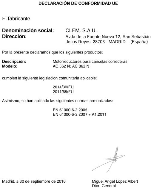
Figure 4: EU Declaration of Conformity for CLEMSA AC 562 N and AC 862 N motors, dated September 30, 2016, confirming compliance with directives 2014/30/EU and 2011/65/EU, and harmonized standards EN 61000-6-2:2005 and EN 61000-6-3:2007 + A1:2011. Signed by Miguel Angel López Albert, General Director of CLEM, S.A.U.
11. Warranty and Support
For warranty information, technical support, or spare parts, please contact your CLEMSA dealer or the manufacturer directly. Keep your purchase receipt as proof of purchase.
Manufacturer: CLEMSA
First Available Date: March 26, 2024


