
PowMr New 30amp 12V24V36V48V
Contents
PowMr 30A PWM Solar Charge Controller User Manual
Model: New 30amp 12V24V36V48V
Brand: PowMr
1. Introduction
The PowMr 30A PWM Solar Charge Controller is an advanced and efficient device designed to manage the power flow from your solar panels to your battery bank. It automatically detects 12V, 24V, 36V, and 48V systems and is compatible with a wide range of battery types, including Flooded, AGM, GEL, LifePO4, Lithium, and user-defined settings. Featuring a built-in LCD display and dual USB outputs, this controller provides real-time monitoring, parameter configuration, and convenient charging for external devices. Its robust multi-protection functions ensure the safety and longevity of your photovoltaic system.
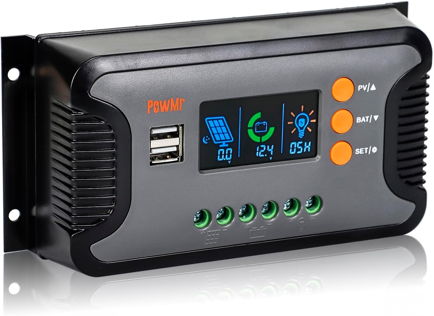
Figure 1: PowMr 30A PWM Solar Charge Controller
2. Key Features
- Automatic System Voltage Detection: Auto-detects 12V, 24V, 36V, and 48V systems.
- High Charging Current: Rated charging current of 30A.
- Wide PV Input Voltage: Max. PV Input Voltage up to 100V.
- Dual USB Outputs: Built-in 2 USB ports with 5V/2A output for charging mobile devices.
- LCD Display: User-friendly setup with real-time monitoring and parameter configuration.
- 3-Stage PWM Technology: Features Bulk charge, Boost charge, and Float charge modes for optimized battery charging and extended battery life.
- Broad Battery Compatibility: Adaptable to User, Flooded, AGM, GEL, LifePO4, Lithium, and other customized battery types.
- Multiple Protection Functions: Includes overcharge protection, over-discharge protection, overload protection, short circuit protection, and reverse current protection to enhance system safety.

Figure 2: Compatibility with 12V/24V/36V/48V battery systems including LiFePO4, GEL, Flooded, and Lithium.

Figure 3: Multi-protection functions including short-circuit, overload, over-current, over-discharge, reversed polarity, and over-temperature protection.
3. Product Overview
3.1 Interface Description
The controller features a clear layout for easy connection and operation. Below is a description of its main components:

Figure 4: Controller Interface showing USB ports, LCD display, function keys, PV input port, Battery port, Load port, and heat sink.
- USB Port: For charging external USB devices (5V/2A).
- LCD Display: Shows real-time system parameters and status.
- Function Keys: Buttons for navigation and parameter settings (PV/A, BAT/V, SET/←).
- Mounting Hole: For securing the controller to a surface.
- PV Input Port: Connects to solar panels.
- Battery Port: Connects to the battery bank.
- Load Port: Connects to DC loads.
- Heat Sink: Dissipates heat for optimal performance.
4. Setup & Installation
4.1 Important Safety Information
- Ensure all connections are tight and correct to avoid damage.
- Always connect the battery to the controller FIRST, then the solar panel, and finally the load.
- Disconnect in reverse order: load, then solar panel, then battery.
- Install the controller in a well-ventilated area, away from direct sunlight and moisture.
- Use appropriate wire gauges for your system's current and distance.
4.2 Wiring Diagram
The following diagram illustrates the correct connection order for your solar charge controller:

Figure 5: Connection diagram showing the order: Battery ①, Solar Panels ②, Load ③.
4.3 Installation Steps
Follow these steps for proper installation:
- Mount the Controller: Secure the controller to a wall or suitable surface using four screws through the mounting holes.
- Connect the Battery: Connect the battery cables to the battery port on the controller. Ensure correct polarity (positive to positive, negative to negative).
- Connect the Solar Panels: Connect the solar panel cables to the PV input port on the controller. Ensure correct polarity.
- Connect the DC Load: Connect your DC loads to the load port on the controller. Ensure correct polarity.
- Power On: Close the battery circuit breaker to power on the controller. The LCD display should illuminate.
Video 1: PWM Solar Charge Controller Quick Installation Wiring Guide. This video demonstrates the physical installation and wiring steps for the solar charge controller.
5. Operating Instructions
5.1 LCD Display
The LCD display provides comprehensive information about your solar system's status. Use the function keys to navigate through different screens and settings.

Figure 6: Backlight LCD Screen with display elements.
- Day/Night State: Indicates whether the system is operating in day or night mode.
- PV Parameter: Displays current solar panel voltage and current.
- Battery Capacity: Shows the current charge level of the battery.
- Battery Parameter: Displays battery voltage and charging current.
- Normal/Fault State: Indicates normal operation or displays fault codes if an issue occurs.
- DC Parameter: Shows load current and status.
5.2 Parameter Settings
The controller allows for customization of various parameters to suit your specific battery type and system requirements. Refer to the detailed manual included with your product for specific navigation and setting instructions. Generally, you can adjust settings such as battery type, charge voltage limits, and load control modes.
6. Maintenance
Regular maintenance ensures the optimal performance and longevity of your solar charge controller:
- Inspect Connections: Periodically check all wiring connections for tightness and corrosion. Loose connections can cause overheating and damage.
- Clean the Controller: Keep the controller clean and free from dust and debris. Use a dry cloth to wipe the surface. Ensure ventilation openings are not blocked.
- Monitor Performance: Regularly check the LCD display for normal operation and any fault indicators. Compare readings with expected values.
- Battery Health: Monitor your battery's health and voltage. Ensure it is within the recommended operating range for its type.
- Environmental Conditions: Ensure the installation environment remains within the specified temperature and humidity ranges.
7. Troubleshooting
This section provides solutions to common issues you might encounter with your solar charge controller. For more complex problems, please contact customer support.
| Problem | Possible Cause | Solution |
|---|---|---|
| Controller not powering on | Battery not connected or low voltage; reversed battery polarity; faulty wiring. | Check battery connections and voltage; ensure correct polarity; inspect wiring for damage. |
| No charging from solar panels | Solar panels not connected; insufficient sunlight; reversed PV polarity; faulty solar panel. | Check PV connections; ensure adequate sunlight; verify PV polarity; test solar panels. |
| Load not working | Load not connected; overload protection activated; battery low voltage protection. | Check load connections; reduce load; charge battery. |
| LCD display shows error code | Specific system fault (e.g., over-voltage, short-circuit). | Refer to the full user manual for specific error code meanings and solutions. Address the underlying fault. |
8. Specifications
| Feature | Description |
|---|---|
| Rated Charging Current | 30A |
| System Voltage | 12V / 24V / 36V / 48V Auto |
| Max. PV Input Voltage | 100V |
| Max. Input Power (12V System) | 360W |
| Max. Input Power (24V System) | 720W |
| Max. Input Power (36V System) | 1080W |
| Max. Input Power (48V System) | 1440W |
| USB Output | Dual 5V/2A |
| Battery Types Supported | User, Flooded, AGM, GEL, LifePO4, Lithium |
| Charging Port Type | MC4, Battery Cables |
| Package Dimensions | 8.07 x 4.25 x 2.56 inches |
| Item Weight | 1.01 pounds |
| Country of Origin | China |
| Display Type | LCD |
9. Warranty & Support
PowMr products are designed for reliability and performance. For information regarding product warranty, technical support, or service, please refer to the warranty card included with your product or visit the official PowMr website. Our customer service team is available to assist you with any questions or issues you may encounter.
For further assistance, please contact:
- PowMr Customer Support
- Website: PowMr Official Store
Ask a question about this manual
Ask about setup, troubleshooting, compatibility, parts, safety, or missing instructions. Manuals+ will review the question and use this page’s manual context to help answer it.