
1. Introduction
The D YEDEMC OPM-VFL-1 is a portable, multi-functional optical fiber testing device designed for comprehensive fiber optic network analysis. This integrated unit combines an Optical Power Meter (OPM), a Visual Fault Locator (VFL), and an RJ45 cable tester. It is suitable for continuous optical signal power measurement, optical fiber link loss testing, and optical fiber line continuity testing. Its compact design, durable construction, and user-friendly interface make it an essential tool for optical cable construction, maintenance, communication, sensing, and CATV applications.

Figure 1: D YEDEMC OPM-VFL-1 Fiber Optic Cable Tester main unit.
2. Key Features
- Multi-Functionality: Integrates Optical Power Meter (OPM), Visual Fault Locator (VFL), and RJ45 cable testing capabilities.
- Wavelength Measurement: Supports 8 standard wavelengths: 850nm, 980nm, 1300nm, 1310nm, 1490nm, 1550nm, 1625nm, and 1650nm.
- Wide Test Range: Optical power measurement range of -70dBm to +6dBm.
- Universal Interface: Compatible with FC, SC, and ST optical connectors.
- Display Modes: Simultaneous display of linear mW and non-linear dBm values.
- User-Friendly Features: Includes lighting, automatic shutdown, backlight display, wavelength memory function, and user calibration support.
- Durable Design: Advanced thermoplastic molding for protection and ergonomic handling.
- Power Options: Supports external power supply via charging treasure or computer.

Figure 2: Overview of the device's optical ports and their functions.
3. Setup
- Battery Installation: The device requires two AA dry batteries (not included). Open the battery compartment cover on the back of the unit, insert the batteries according to the polarity indicators, and close the cover securely.
- Power On: Press and hold the power button (U symbol) to turn on the device.
- Initial Check: Upon powering on, the display will illuminate, showing the current wavelength and measurement mode.
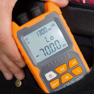
Figure 3: The compact size of the OPM-VFL-1, suitable for portability.
4. Operating Instructions
4.1. Optical Power Meter (OPM) Function
- Connect Fiber: Remove the dust cap from the "Power Meter" port (left port, typically labeled OPM-A) and connect the fiber optic cable to be tested. Ensure the connector type (FC/SC/ST) is compatible.
- Select Wavelength: Press the "λ" button to cycle through the available wavelengths (850nm, 980nm, 1300nm, 1310nm, 1490nm, 1550nm, 1625nm, 1650nm) until the desired wavelength is displayed.
- Read Measurement: The display will show the optical power in dBm and mW.
- Set Reference (Optional): For relative power measurements, press the "REF" button to set the current power as the reference point (0dB). Subsequent measurements will show the loss or gain relative to this reference.

Figure 4: Optical Power Meter function in use, showing power readings.
4.2. Visual Fault Locator (VFL) Function
- Connect Fiber: Remove the dust cap from the "VFL" port (right port, typically labeled VFL-A) and connect the fiber optic cable.
- Activate VFL: Press the "LED" button to activate the Visual Fault Locator. The VFL typically operates at 650nm with 1mW output.
- Mode Selection: Repeatedly press the "LED" button to cycle through VFL modes: continuous light, flashing light, and off.
- Fault Detection: Observe the fiber for any visible red light leakage, which indicates breaks, bends, or poor connections.

Figure 5: Visual Fault Locator (VFL) function active, showing red light output.
4.3. RJ45 Cable Testing Function
- Connect RJ45 Cable: Connect one end of the RJ45 cable to the RJ45 port on the main unit (located at the bottom). Connect the other end of the RJ45 cable to the remote unit.
- Initiate Test: The device will automatically begin testing the RJ45 cable.
- Observe Indicators: The LED indicators (1-8) on both the main unit and the remote unit will light up sequentially, indicating the continuity of each wire pair. Any unlit or incorrectly lit LEDs indicate a fault (e.g., open, short, cross).

Figure 6: RJ45 cable testing in progress with the main unit and remote tester.

Figure 7: Bottom view of the device, highlighting the RJ45 and charging ports.
4.4. Additional Functions
- Backlight: Press the "LIGHT" button to toggle the display backlight on or off.
- Lighting: The device may include an integrated LED light for illuminating work areas. Activate it by pressing the "LIGHT" button (may require a long press or specific sequence).
- Auto-Off: The device features an automatic shutdown function after 10 minutes of inactivity to conserve battery life.
Official Product Video: D YEDEMC Mini Optical Fiber Power Meter
This video demonstrates the basic functions and operation of the D YEDEMC Mini Optical Fiber Power Meter, including its use for optical power measurement and visual fault location.
5. Maintenance
- Cleaning: Regularly clean the device's exterior with a soft, dry cloth. Avoid using abrasive cleaners or solvents.
- Optical Port Care: Always keep the dust caps on the optical ports when not in use to prevent dust and debris from entering, which can affect measurement accuracy. Use specialized fiber optic cleaning tools if necessary.
- Battery Replacement: Replace batteries when the low battery indicator appears on the display to ensure accurate operation.
- Storage: Store the device in a cool, dry place, away from direct sunlight and extreme temperatures.
6. Troubleshooting
- Device Does Not Power On:
- Check if batteries are installed correctly and have sufficient charge. Replace if necessary.
- Inaccurate OPM Readings:
- Ensure optical connectors are clean and properly seated.
- Verify the correct wavelength is selected for the measurement.
- Perform user calibration if readings are consistently off.
- VFL Red Light Not Visible:
- Ensure the VFL function is activated (LED button pressed).
- Check the fiber connection to the VFL port.
- RJ45 Test Failure:
- Verify both ends of the RJ45 cable are securely connected to the main unit and the remote unit.
- Inspect the RJ45 cable for visible damage.
7. Specifications
| Parameter | Value |
|---|---|
| Calibration Wavelength | 800~1700nm |
| Optical Connector | FC/SC/ST Universal Interface |
| Detector Type | InGaAs |
| Measurement Range | -70 ~ +6dBm |
| Accuracy | ±0.05dB |
| Standard Wavelengths | 850, 980, 1300, 1310, 1490, 1550, 1625, 1650nm |
| Display Resolution | mW: 0.1%, dBm: 0.01dBm |
| Integrated Functions | OPM, VFL, and RJ45 |
| Working Temperature | -10~+60℃ |
| Storage Temperature | -30~+70℃ |
| Auto-Off Time | 10 Minutes |
| Battery Operating Time | ≥72 hours |
| Dimensions | 11.2 x 6.6 x 3 cm |
| Weight | 140g |
| Power Source | 2x AA Batteries |
8. Customer Support
For any questions, issues, or technical assistance regarding your D YEDEMC Fiber Optic Cable Tester, please contact our customer service team. We are committed to providing lifetime friendly customer service to ensure your satisfaction.
Please refer to the product packaging or the retailer's website for specific contact information.