MASTECH M266C Digital Clamp Meter User Manual
Model: GL-M266C
Professional Electrical Tool for Current, Voltage, and Circuit Testing
1. Introduction
Thank you for choosing the MASTECH M266C Digital Clamp Meter. This instrument is a professional, portable measuring device designed for electrical testing. It offers high accuracy, stability, and reliability, making it an ideal tool for electricians, technicians, and DIY enthusiasts.
The M266C is capable of measuring AC/DC voltage, AC current, resistance, continuity, and temperature. Its robust design and user-friendly interface ensure safe and efficient operation.
Key Features:
- Display: 2000 counts for clear readings.
- Jaw Opening: Φ50mm (2.0") for large conductors.
- Continuity Buzzer: Audible indication for circuits with resistance less than 100Ω.
- Data Hold: Freezes the displayed reading for convenient recording.
- Low Battery Display: Indicates when batteries need replacement.
- Insulation Test capability.
- Safety Rating: CAT II 1000V / CAT III 600V.
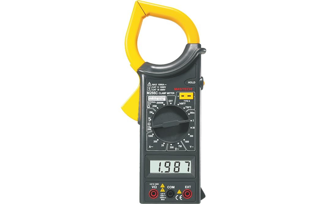
Figure 1: Front view of the MASTECH M266C Digital Clamp Meter.
2. Safety Information
WARNING: To avoid possible electric shock or personal injury, and to avoid possible damage to the meter or to the equipment under test, follow these safety rules:
- Read this manual thoroughly before using the meter.
- Do not apply more than the rated voltage, as marked on the meter, between terminals or between any terminal and earth ground.
- Use caution when working with voltages above 60V DC or 30V AC RMS. Such voltages pose a shock hazard.
- Before measuring current, ensure the circuit is de-energized and the clamp jaw is fully closed around a single conductor.
- Always disconnect the test leads from the circuit before changing functions or ranges.
- Do not use the meter if it appears damaged or if the insulation on the test leads is damaged.
- Ensure the battery cover is securely closed before operation.
- Observe the input limits for each function as specified in the specifications section.
3. Setup and Battery Installation
3.1 Unpacking
Carefully unpack the meter and check for any damage. Verify that all accessories listed in the packaging information are present.
3.2 Battery Installation
The M266C requires 2 LR44 batteries (included). To install or replace batteries:
- Ensure the meter is turned OFF.
- Locate the battery compartment on the back of the meter.
- Use a screwdriver to loosen the screw on the battery cover.
- Remove the battery cover.
- Insert the 2 LR44 batteries, observing the correct polarity (+/-) as indicated inside the compartment.
- Replace the battery cover and tighten the screw securely.
When the low battery indicator appears on the display, replace the batteries immediately to ensure accurate readings.
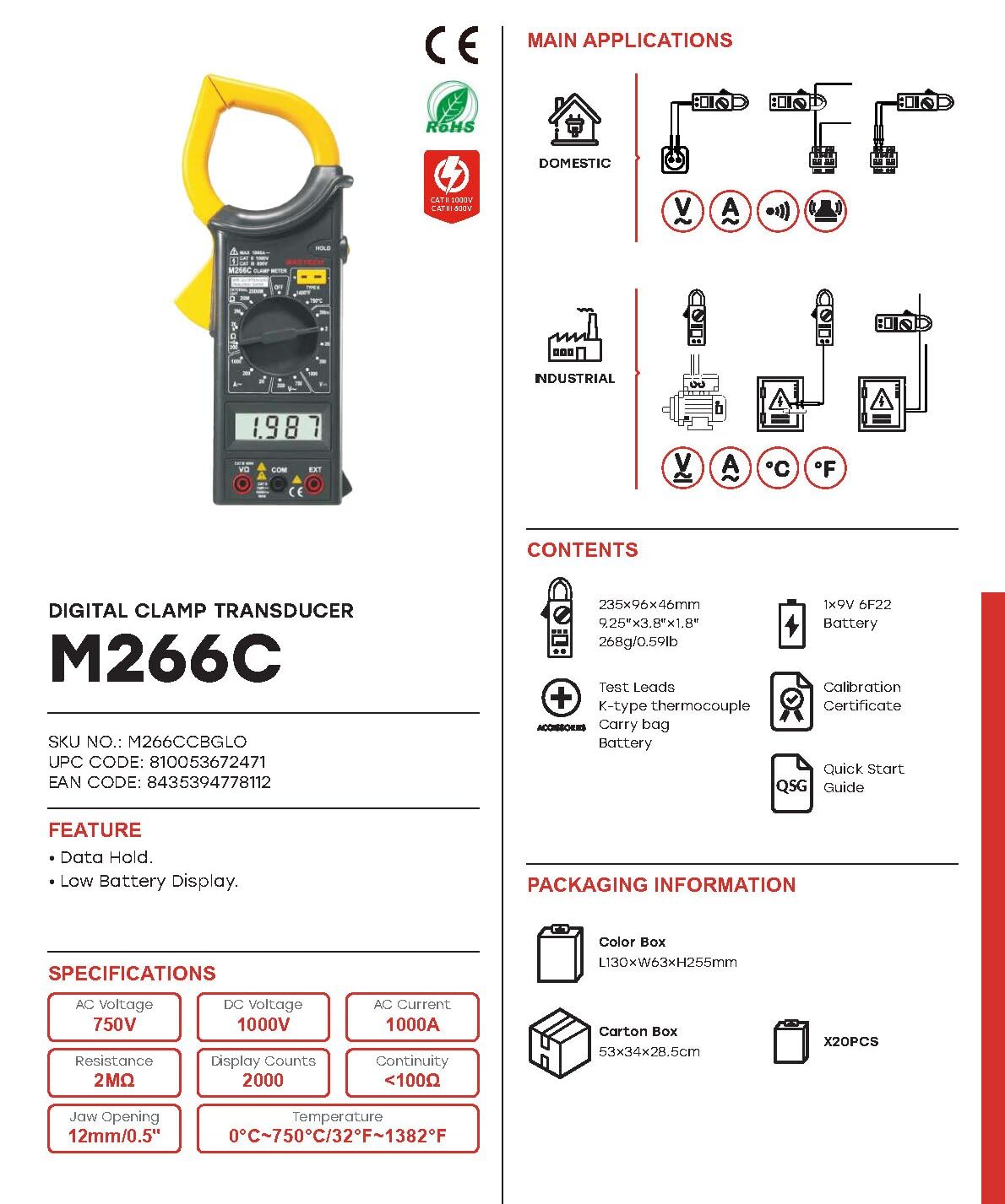
Figure 2: M266C packaging contents and basic specifications.
4. Operating Instructions
4.1 General Operation
- Power ON/OFF: Rotate the function dial from the OFF position to any desired measurement function to turn the meter ON. Rotate it back to OFF to turn the meter OFF.
- Function Selection: Turn the rotary switch to select the desired measurement function (e.g., V~ for AC Voltage, A~ for AC Current, Ω for Resistance).
- Data Hold: Press the 'HOLD' button to freeze the current reading on the display. Press it again to release.
4.2 AC Current Measurement (A~)
- Set the rotary switch to the desired AC Current range (e.g., 200A or 1000A).
- Open the clamp jaw by pressing the trigger.
- Place the clamp jaw around a single conductor of the circuit to be measured. Ensure the jaw is completely closed.
- Read the AC current value on the display.
4.3 AC/DC Voltage Measurement (V~ / V-)
- Insert the red test lead into the 'VΩ' input jack and the black test lead into the 'COM' input jack.
- Set the rotary switch to the desired AC Voltage (V~) or DC Voltage (V-) range.
- Connect the test leads in parallel to the circuit or component to be measured.
- Read the voltage value on the display.
4.4 Resistance Measurement (Ω)
- Insert the red test lead into the 'VΩ' input jack and the black test lead into the 'COM' input jack.
- Set the rotary switch to the desired Resistance (Ω) range.
- Ensure the circuit is de-energized before measuring resistance.
- Connect the test leads across the component to be measured.
- Read the resistance value on the display.
4.5 Continuity Test (<100Ω)
- Insert the red test lead into the 'VΩ' input jack and the black test lead into the 'COM' input jack.
- Set the rotary switch to the Continuity function (often indicated by a speaker symbol).
- Ensure the circuit is de-energized.
- Connect the test leads across the circuit or component.
- If the resistance is less than approximately 100Ω, the buzzer will sound, indicating continuity.
4.6 Temperature Measurement (°C / °F)
The M266C supports temperature measurement using a K-type thermocouple (often included).
- Set the rotary switch to the Temperature function (°C or °F).
- Insert the K-type thermocouple into the designated input jacks (usually labeled 'TEMP' or similar, or use the 'VΩ' and 'COM' jacks if specified for temperature).
- Place the tip of the thermocouple on or near the object whose temperature is to be measured.
- Read the temperature value on the display.
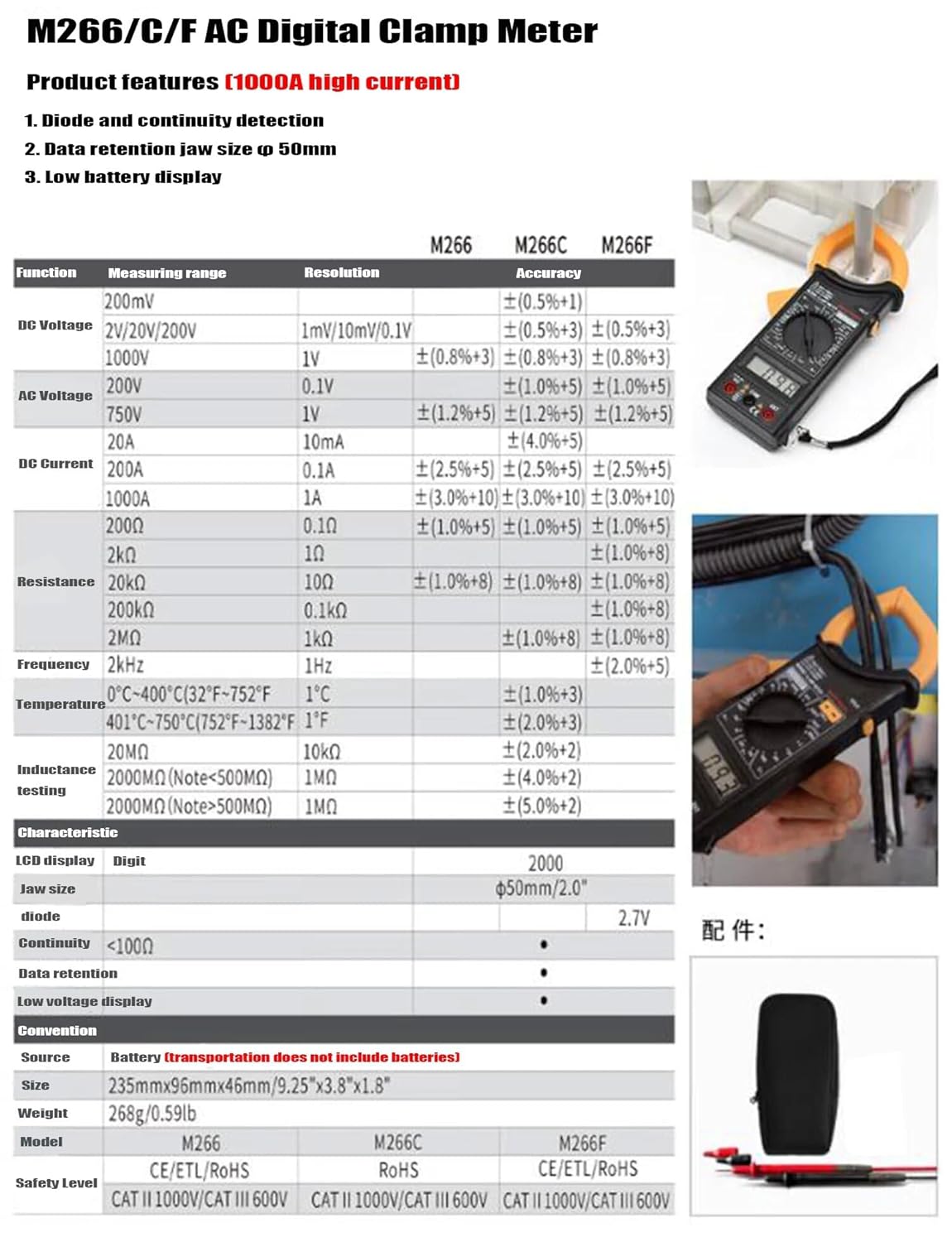
Figure 3: M266C/F AC Digital Clamp Meter product features and detailed specifications table.
5. Specifications
| Parameter | Specification |
|---|---|
| Display | 2000 Counts |
| Jaw Opening | Φ50mm / 2.0" |
| DC Voltage (V-) | 200mV, 2V, 20V, 200V, 1000V |
| AC Voltage (V~) | 200V, 750V |
| DC Current (A-) | 200A, 1000A |
| AC Current (A~) | 200A, 1000A |
| Resistance (Ω) | 200Ω, 2kΩ, 20kΩ, 200kΩ, 2MΩ, 20MΩ |
| Continuity Buzzer | <100Ω |
| Temperature | 0°C ~ 400°C (32°F ~ 752°F) and 401°C ~ 750°C (752°F ~ 1382°F) |
| Insulation Test | 20MΩ, 2000MΩ (Note: <500MΩ) |
| Power Source | 2 x LR44 Batteries (included) |
| Dimensions (L x W x H) | 6.3 x 3.54 x 1.97 inches (235mm x 96mm x 46mm) |
| Item Weight | 1.1 Pounds (0.5 Kilograms) |
| Safety Level | CAT II 1000V / CAT III 600V |
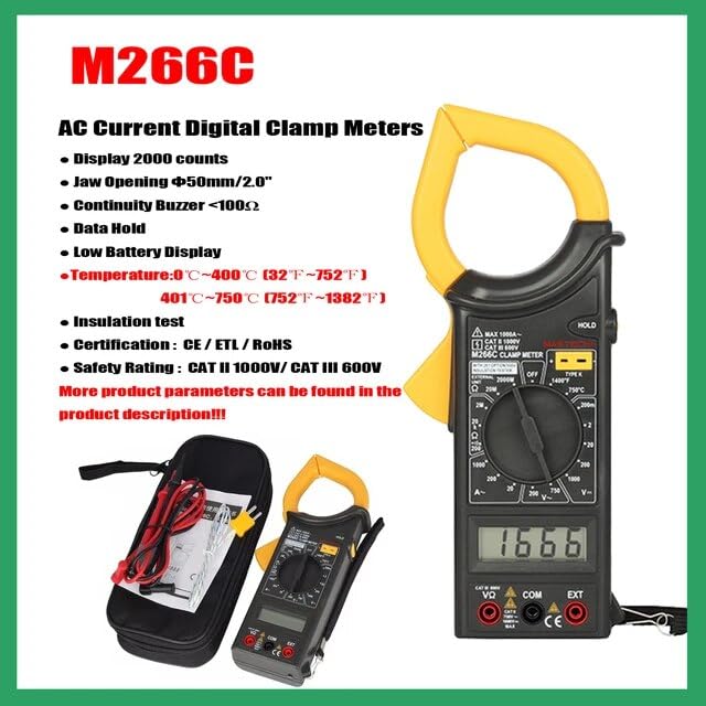
Figure 4: Key features of the M266C model.
6. Maintenance
6.1 Cleaning
To clean the meter, wipe the case with a damp cloth and mild detergent. Do not use abrasives or solvents. Ensure the meter is completely dry before use.
6.2 Battery Replacement
As mentioned in Section 3.2, replace the batteries when the low battery indicator appears on the display to ensure accurate readings and proper operation.
6.3 Storage
If the meter is not to be used for a long period, remove the batteries to prevent leakage and damage to the meter. Store the meter in a cool, dry place, away from direct sunlight and extreme temperatures.
7. Troubleshooting
| Problem | Possible Cause | Solution |
|---|---|---|
| Meter does not power on | Dead or incorrectly installed batteries | Check battery polarity; replace batteries. |
| Low Battery indicator | Batteries are low | Replace batteries immediately. |
| No reading or 'OL' displayed | Overload, open circuit, or incorrect range | Select a higher range; check circuit for open; ensure clamp jaw is fully closed around a single conductor for current measurements. |
| Inaccurate readings | Low battery, external interference, or incorrect connection | Replace batteries; move away from strong electromagnetic fields; ensure proper test lead connection. |
8. Warranty and Support
For warranty information and technical support, please refer to the documentation included with your purchase or visit the official Mastech website. Keep your purchase receipt as proof of purchase for any warranty claims.
Mastech Official Website: Visit the Mastech Store on Amazon