Introduction
Thank you for choosing the Mastech MS8233D Digital Multimeter. This manual provides essential information for the safe and effective operation, maintenance, and troubleshooting of your device. Please read this manual thoroughly before use and keep it for future reference.
Safety Information
WARNING: To avoid electric shock or personal injury, read and understand all safety information before using this product.
- Always ensure the multimeter is in the correct function and range before making measurements.
- Do not apply more than the rated voltage, as marked on the meter, between terminals or between any terminal and earth ground. The MS8233D has a Safety Rating of CATII 600V.
- Use caution when working with voltages above 30V AC RMS, 42V peak, or 60V DC. Such voltages pose a shock hazard.
- Keep your fingers behind the probe barriers during measurements.
- Do not use the meter if it is damaged or if the case is open. Inspect the meter and test leads before use.
- Replace the battery immediately when the low battery indicator appears to ensure accurate readings.
- Do not operate the meter in explosive gas, vapor, or dust environments.
Key Features
The Mastech MS8233D Digital Multimeter offers a range of functionalities for various electrical measurements:
- Display: 2000 counts for precise readings.
- Ranging: Auto and Manual Ranging capabilities.
- Diode Test: Features a Diode Open Voltage of 1.5V.
- Continuity Test: Audible buzzer for resistance less than 60Ω.
- Data Hold: Freezes the displayed reading for convenience.
- Auto Power Off: Conserves battery life.
- Non-contact Voltage Detection (NCV): For identifying live wires without direct contact.
- Maximum Measurement: Records the highest value measured.
- Display Backlight: For visibility in low-light conditions.
- Low Battery Display: Indicates when battery replacement is needed.
- Power Supply: Operates on 1x 9V 6F22 Battery.
- Certifications: RoHS compliant.
- Safety Rating: CATII 600V.
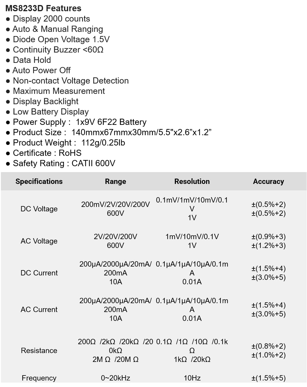
Figure 1: Front view of the Mastech MS8233D Digital Multimeter, highlighting the display, rotary function switch, and input terminals.
Product Overview and Components
The MS8233D multimeter is designed for ease of use and durability. Familiarize yourself with its main parts:

Figure 2: Overview of the MS8233D Digital Multimeter, illustrating its physical dimensions, power supply, and typical applications in domestic, industrial, and electronics settings.
- LCD Display: Shows measurement readings, units, and function indicators.
- Function Rotary Switch: Used to select the desired measurement function (e.g., ACV, DCV, Resistance, Diode, Continuity, Temperature, NCV).
- Input Jacks: Terminals for connecting test leads.
- COM Jack: Common (negative) input terminal for all measurements.
- VΩmA Jack: Positive input terminal for voltage, resistance, diode, continuity, and small current measurements.
- 10A Jack: Positive input terminal for high current (up to 10A) measurements.
- Function Buttons: For features like Data Hold, Backlight, and Range selection.
Setup
Battery Installation
The MS8233D requires one 9V 6F22 battery for operation. To install or replace the battery:
- Ensure the multimeter is turned off and disconnect all test leads from the input terminals.
- Locate the battery compartment cover on the back of the meter.
- Use a screwdriver to loosen the screw(s) on the battery cover and remove the cover.
- Connect the new 9V battery to the battery clips, observing the correct polarity.
- Place the battery into the compartment and replace the cover, securing it with the screw(s).
Note: The meter includes a low battery indicator. Replace the battery promptly when this indicator appears to maintain measurement accuracy.
Operating Instructions
Before making any measurement, ensure the test leads are properly connected and the function switch is set to the desired range.
Measuring DC Voltage (DCV)
- Insert the red test lead into the VΩmA jack and the black test lead into the COM jack.
- Set the rotary switch to the desired DCV range (e.g., 200mV, 2V, 20V, 200V, 600V). If unsure, start with the highest range or use auto-ranging if available.
- Connect the test probes across the component or circuit to be measured, observing polarity.
- Read the voltage value on the LCD display.
Measuring AC Voltage (ACV)
- Insert the red test lead into the VΩmA jack and the black test lead into the COM jack.
- Set the rotary switch to the desired ACV range (e.g., 2V, 20V, 200V, 600V).
- Connect the test probes across the component or circuit to be measured.
- Read the voltage value on the LCD display.
Measuring DC/AC Current (DCA/ACA)
CAUTION: Never connect the meter in parallel to a voltage source when measuring current. This can damage the meter and the circuit.
- For currents up to 200mA, insert the red test lead into the VΩmA jack. For currents up to 10A, insert the red test lead into the 10A jack. Insert the black test lead into the COM jack.
- Set the rotary switch to the desired DC or AC current range (e.g., 200µA, 2000µA, 20mA, 200mA, 10A).
- Open the circuit where current is to be measured and connect the meter in series with the load.
- Read the current value on the LCD display.
Measuring Resistance (Ω)
- Insert the red test lead into the VΩmA jack and the black test lead into the COM jack.
- Set the rotary switch to the desired Resistance range (e.g., 200Ω, 2kΩ, 20kΩ, 200kΩ, 2MΩ, 20MΩ).
- Ensure the circuit or component is de-energized before measuring resistance.
- Connect the test probes across the component.
- Read the resistance value on the LCD display.
Diode Test
- Insert the red test lead into the VΩmA jack and the black test lead into the COM jack.
- Set the rotary switch to the Diode symbol (usually shared with Continuity).
- Connect the red probe to the anode and the black probe to the cathode of the diode.
- The display will show the forward voltage drop. Reverse the probes; the display should show 'OL' (Open Loop) for a good diode.
Continuity Test
- Insert the red test lead into the VΩmA jack and the black test lead into the COM jack.
- Set the rotary switch to the Continuity symbol (usually shared with Diode).
- Connect the test probes across the circuit or component.
- If the resistance is below approximately 60Ω, the buzzer will sound, indicating continuity. The display will also show the resistance value.
Non-Contact Voltage (NCV) Detection
- Set the rotary switch to the NCV function.
- Move the top part of the meter (NCV sensor area) close to the conductor suspected of having AC voltage.
- The meter will emit an audible beep and the NCV indicator will light up if AC voltage is detected.
Data Hold Function
Press the 'HOLD' button to freeze the current reading on the display. Press it again to release the hold and resume live measurements.
Backlight Function
Press the 'LIGHT' button to turn on the display backlight. Press it again to turn it off. The backlight may automatically turn off after a short period to conserve battery.
Maintenance
Cleaning
Wipe the meter's case with a damp cloth and a mild detergent. Do not use abrasives or solvents. Ensure the meter is completely dry before use.
Battery Replacement
Refer to the 'Battery Installation' section under 'Setup' for instructions on replacing the 9V battery. Always replace the battery when the low battery indicator is displayed to ensure accurate readings and proper operation.
Fuse Replacement
The MS8233D is equipped with internal fuses to protect against overcurrent. If the current measurement function stops working, the fuse may need replacement. Fuse replacement should only be performed by qualified personnel. Use only fuses of the specified type and rating (e.g., F200mA/250V for mA range, F10A/250V for 10A range).
Troubleshooting
| Problem | Possible Cause | Solution |
|---|---|---|
| No display or dim display | Dead or low battery | Replace the 9V battery. |
| Incorrect readings | Incorrect function/range selected; poor test lead connection; low battery | Verify function and range; check test lead connections; replace battery. |
| Current measurement not working | Blown fuse | Replace the appropriate fuse (refer to Maintenance section). |
| 'OL' (Overload) displayed | Measurement exceeds selected range; open circuit (for continuity/resistance) | Select a higher range; check for open circuit. |
| No continuity beep | Resistance too high; open circuit | Check for continuity; ensure resistance is below 60Ω. |
Specifications
The following table details the measurement ranges, resolutions, and accuracies for the Mastech MS8233D Digital Multimeter:

Figure 3: Comprehensive specifications for the MS8233D, outlining measurement capabilities and precision.
| Feature | Specification |
|---|---|
| Display | 2000 counts |
| DC Voltage | 200mV / 2V / 20V / 200V / 600V |
| AC Voltage | 2V / 20V / 200V / 600V |
| DC Current | 200µA / 2000µA / 20mA / 200mA / 10A |
| AC Current | 200µA / 2000µA / 20mA / 200mA / 10A |
| Resistance | 200Ω / 2kΩ / 20kΩ / 200kΩ / 2MΩ / 20MΩ |
| Frequency | 0-20kHz |
| Diode Open Voltage | 1.5V |
| Continuity Buzzer | <60Ω |
| Power Supply | 1x 9V 6F22 Battery |
| Product Dimensions | 140mm x 67mm x 30mm (5.5" x 2.6" x 1.2") |
| Product Weight | 112g (0.25lb) |
| Safety Rating | CATII 600V |
| Certifications | CE, RoHS |
Warranty and Support
For warranty information and technical support, please refer to the documentation provided with your purchase or contact the seller/manufacturer directly. Keep your purchase receipt as proof of purchase for any warranty claims.


