
1. Introduction
This manual provides essential information for the safe and efficient installation, operation, and maintenance of the Xerial SA5000 Flow Sensor. Please read this manual thoroughly before using the device and keep it for future reference. The SA5000 is designed for precise flow measurement in various industrial applications.
2. Safety Information
Always observe the following safety precautions to prevent personal injury and damage to the equipment:
- Installation and maintenance should only be performed by qualified personnel.
- Ensure the power supply is disconnected before performing any wiring or maintenance.
- Verify that the operating conditions (pressure, temperature, flow rate) are within the sensor's specified limits.
- Protect the sensor from mechanical shock and excessive vibration.
- Do not modify the sensor in any way. Unauthorized modifications will void the warranty.
3. Product Overview
The Xerial SA5000 is a robust flow sensor designed for reliable performance in demanding environments. It features a compact design, an integrated display, and multiple output options including IO-Link.
3.1 Key Features
- Model: SA5000
- Integrated display for local indication
- IO-Link 1.1 communication interface
- Switching and frequency outputs
- 4-20 mA analog output
- Durable stainless steel construction
- High ingress protection ratings (IP65/IP67)
3.2 Sensor Components

Figure 1: Xerial SA5000 Flow Sensor showing the display, control buttons, and M12 connector.
The sensor features a robust metal housing, a flow sensing probe, an integrated digital display for real-time readings, and three control buttons for configuration. Electrical connection is made via a standard M12 circular connector.

Figure 2: Side view of the SA5000 sensor, highlighting the product label with IO-Link compatibility and basic wiring information.
The side of the sensor includes a label detailing its model number, certifications, and basic wiring pinout for easy reference during installation.
4. Specifications
| Parameter | Value |
|---|---|
| Model | SA5000 |
| Manufacturer | Xerial |
| ASIN | B0CYQ2K6L7 |
| UPC | 742440236112 |
| Certifications | CE, UL US LISTED, IO-Link 1.1, UK CA, EAC |
| Ingress Protection | IP65, IP67 |
| Electrical Current (EQ) | 11mA |
| Outputs | Switching, Frequency, 4-20 mA, IO-Link |
| Country of Origin | Germany |
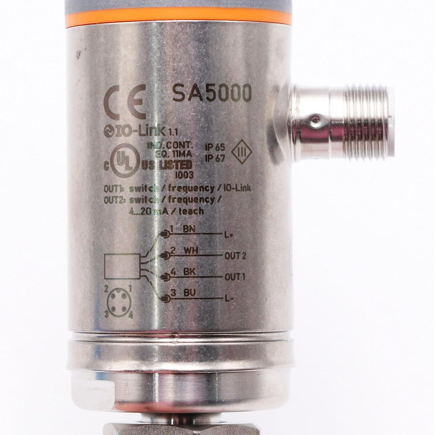
Figure 3: Detailed view of the SA5000 product label, showing certifications, IP ratings, and the electrical wiring diagram.

Figure 4: Packaging label for the SA5000, indicating "Made in Germany" and additional certifications like UK CA and EAC.
The product label and packaging provide critical information regarding the sensor's compliance, electrical characteristics, and country of origin. Always refer to these for specific details during installation and operation.
5. Setup & Installation
5.1 Mounting
The SA5000 flow sensor is designed for insertion into a pipe or conduit. Ensure the mounting location provides adequate space for installation, maintenance, and visibility of the display. The sensor should be mounted in a section of pipe where the flow is fully developed and free from turbulence caused by bends, valves, or pumps. Use appropriate fittings to secure the sensor and ensure a leak-free connection.
5.2 Electrical Connection
The sensor uses an M12 connector for electrical connections. Refer to the wiring diagram on the sensor label and below for correct pin assignments. Ensure the power supply meets the sensor's requirements before connecting.
- Pin 1 (BN - Brown): L+ (Power Supply Positive)
- Pin 2 (WH - White): OUT2 (Switch / Frequency / 4-20 mA)
- Pin 3 (BU - Blue): L- (Power Supply Negative)
- Pin 4 (BK - Black): OUT1 (Switch / Frequency / IO-Link)
Connect the sensor to a suitable control system or PLC using a compatible M12 cable. Ensure all connections are secure and properly insulated.
6. Operating Instructions
6.1 Power On
Once properly installed and wired, apply power to the sensor. The integrated display will illuminate and show the current flow rate or other configured parameters. The sensor will begin measuring flow immediately.
6.2 Display and Button Functions
The SA5000 features a digital display and three control buttons for local configuration and monitoring. Specific button functions and menu navigation details are typically found in the detailed programming guide, which can be obtained from the manufacturer's website. Generally, buttons are used for:
- Navigating through display menus.
- Adjusting parameters such as measurement units, switching points, and output types.
- Performing calibration or teach-in functions.
6.3 IO-Link Communication
The SA5000 supports IO-Link 1.1, enabling advanced communication with compatible IO-Link masters. This allows for remote configuration, diagnostics, and process data transmission. For detailed IO-Link setup and parameterization, refer to the IO-Link device description file (IODD) and the IO-Link master's documentation.
7. Maintenance
7.1 Cleaning
Periodically clean the exterior of the sensor with a soft, damp cloth. Do not use abrasive cleaners or solvents that could damage the housing or display. If the sensing element is exposed to the process medium, ensure it is free from buildup or debris that could affect measurement accuracy. Disconnect power before cleaning.
7.2 Inspection
Regularly inspect the sensor for any signs of damage, corrosion, or loose connections. Check the integrity of the cable and connector. Address any issues promptly to ensure continued reliable operation.
8. Troubleshooting
This section provides solutions to common issues. For problems not listed here, contact technical support.
| Problem | Possible Cause | Solution |
|---|---|---|
| No display / No power | Incorrect wiring, no power supply, faulty cable. | Check wiring according to diagram. Verify power supply voltage. Inspect cable for damage. |
| Inaccurate readings | Sensor not properly installed, buildup on sensing element, incorrect calibration. | Ensure correct mounting position. Clean sensing element. Perform calibration if necessary. |
| No output signal | Incorrect output configuration, wiring error, sensor fault. | Check sensor output settings via display or IO-Link. Verify wiring to control system. |
9. Warranty & Support
9.1 Warranty Information
The Xerial SA5000 Flow Sensor comes with a 1-year warranty from the date of purchase, covering defects in materials and workmanship. This warranty does not cover damage caused by improper installation, misuse, unauthorized modification, or external factors such as power surges or physical impact. Please retain your proof of purchase for warranty claims.
9.2 Technical Support
For technical assistance, troubleshooting guidance, or to inquire about warranty service, please contact Xerial customer support. Have your product model number (SA5000) and purchase details ready when contacting support.
Contact information (e.g., phone number, email, website) can typically be found on the manufacturer's official website or product packaging.