
1. Introduction
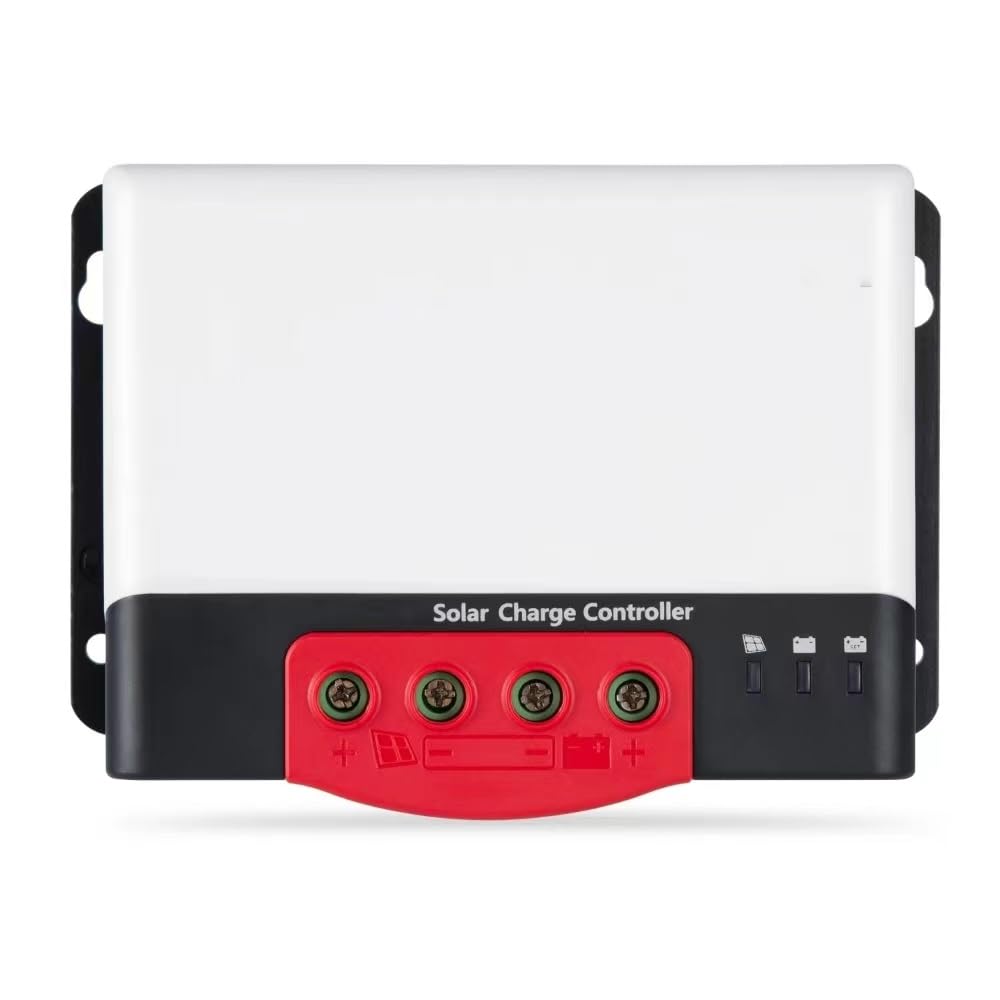
This manual provides essential information for the safe and efficient operation of your Gerrit MC2450N10 MPPT Solar Charge Controller. This device is designed to regulate the power flow from your solar panels to your battery bank, ensuring optimal charging and protecting your batteries from overcharge and over-discharge. It supports 12V and 24V battery systems and is compatible with various battery types including Lithium, Gel, Sealed, and Vented batteries.
2. Safety Instructions
Please read and understand all safety instructions before installation and operation. Failure to follow these instructions may result in electric shock, fire, or severe injury.
- Ensure all connections are tight and correct to prevent loose connections that can cause excessive heat.
- Always disconnect the solar panel and battery power before installing or adjusting the controller.
- Install the controller in a well-ventilated area, away from flammable materials and direct sunlight.
- Do not disassemble or attempt to repair the controller yourself. Contact qualified personnel for service.
- Wear appropriate personal protective equipment, including eye protection, when working with batteries and solar panels.
- Ensure the battery voltage matches the system voltage setting of the controller.
3. Product Features
The Gerrit MC2450N10 MPPT Solar Charge Controller offers advanced features for reliable solar power management:
- Maximum Power Point Tracking (MPPT): Achieves over 99% tracking efficiency to maximize power harvest from solar panels.
- High Charging Conversion Efficiency: Up to 98% charging conversion efficiency.
- Wide Battery Compatibility: Supports Lithium, Gel, Sealed, and Vented battery types.
- System Voltage: Automatic identification for 12V/24V systems.
- Comprehensive Protections: Includes input power limit protection, battery reverse polarity protection, high PV input voltage protection, and over-temperature protection.
- Communication Interface: TTL series communication for external modules (e.g., BT-2, RM-6).
- Robust Design: IP32 waterproof protection level.
4. Setup and Installation
Follow these steps for proper installation of your solar charge controller:
- Mounting: Choose a suitable location for mounting the controller. It should be indoors, protected from direct sunlight, high temperatures, and moisture. Ensure adequate ventilation around the unit.
- Wiring Sequence: Connect components in the following order to prevent damage:
- Connect Battery: First, connect the battery to the controller's battery terminals. Ensure correct polarity (+ to + and - to -). The controller will detect the system voltage (12V or 24V).
- Connect Solar Panels: Next, connect the solar panels to the controller's PV terminals. Ensure correct polarity. Do not exceed the maximum PV open circuit voltage or input power limits.
- Connect Load (Optional): If your model includes a load output, connect your DC load to the load terminals. Ensure correct polarity.
- Verify Connections: Double-check all wiring for correct polarity and secure connections.
5. Operating Instructions
Once installed, the controller operates automatically. It continuously monitors the solar panel output and battery status to ensure efficient charging.
- Charging Process: The MPPT algorithm tracks the maximum power point of the solar panels to deliver the most efficient charge to the battery.
- Battery Type Selection: For optimal performance, ensure the controller is configured for your specific battery type (Lithium, Gel, Sealed, Vented). Refer to the controller's interface or accompanying documentation for battery type setting procedures.
- Indicator Lights: Observe the indicator lights on the controller for status updates regarding solar input and battery charge level.
- Temperature Compensation: The controller features temperature compensation for lead-acid batteries (-3mv/°C/2V default). Lithium batteries typically do not require temperature compensation.
6. Maintenance
Regular maintenance ensures the longevity and optimal performance of your solar charge controller.
- Periodic Inspection: Inspect all wiring and connections every 3-6 months for any signs of damage, corrosion, or loose connections. Tighten any loose terminals.
- Cleaning: Keep the controller's exterior clean and free from dust and debris. Use a dry cloth for cleaning. Do not use liquids or solvents.
- Ventilation: Ensure that the ventilation openings are not blocked to allow for proper heat dissipation.
- Battery Check: Periodically check your battery bank's condition and electrolyte levels (for flooded batteries) as per the battery manufacturer's recommendations.
7. Troubleshooting
This section addresses common issues you might encounter with your solar charge controller.
- System Not Working (No Power):
Possible Cause: Battery reverse polarity.
Solution: Check battery connections. The controller is protected against reverse polarity and will not be damaged, but the system will not operate until corrected. - Charging Power Reduced or Stopped:
Possible Cause: Controller over-temperature.
Solution: Ensure the controller is in a well-ventilated area. Reduce ambient temperature if possible. The controller automatically reduces or stops charging to prevent damage when its internal temperature exceeds the set value. - Solar Panel Power Limited:
Possible Cause: Solar panel input power exceeds the controller's rated value.
Solution: The controller automatically limits the solar panel power within its rated range to prevent over-current damage. This is normal operation under high solar input. - PV Input Automatically Turned Off:
Possible Cause: Voltage at the photovoltaic input terminal is too high.
Solution: Check the open circuit voltage of your solar array. Ensure it does not exceed the controller's maximum PV open circuit voltage (92V at 25°C, 100V at minimum ambient temperature). The controller will automatically disconnect the PV input for protection.
8. Specifications
| Feature | Specification |
|---|---|
| Model | MC2420N10, MC2430N10, MC2440N10, MC2450N10 (This manual focuses on MC2450N10) |
| System Voltage | 12V/24V Auto-detection |
| Battery Voltage Range | 9V-32V |
| Maximum PV Open Circuit Voltage | 92V (at 25°C); 100V (at minimum ambient temperature) |
| PV Input Voltage Range | (Battery voltage +2V) - 72V |
| Rated Charging Current | 50A (for MC2450N10) |
| Maximum Photovoltaic Input Power | 660W/12V; 1320W/24V (for MC2450N10) |
| Charging Conversion Efficiency | 98% |
| MPPT Tracking Efficiency | >99% |
| Temperature Compensation Coefficient | -3mv/°C/2V (default for lead-acid batteries; Lithium batteries have no temperature compensation) |
| Operating Temperature | -35°C to +60°C |
| Protection Level | IP32 |
| Weight | 1335g (for MC2450N10) |
| Communication Method | TTL series communication |
| Operating Altitude | Up to 3000 meters |
| Dimensions (mm) | 183 x 127 x 69.5 (for MC2450N10) |
| Manufacturer | KNOKR |
| Item Model Number (Internal) | KNOKR678 |
| Display Type | Digital (Note: Visual indicators are present, specific digital display functionality may vary or require external module) |
9. Warranty and Support
For warranty information, technical support, or service inquiries, please contact your original point of purchase or the manufacturer directly. Keep your purchase receipt as proof of purchase.