1. Introduction
Thank you for purchasing the Wave KM-127 Blaster Tekkaman Blade plastic model kit. This kit allows you to assemble a highly detailed, non-scale replica of the Blaster Tekkaman Blade from the TV anime "Space Knight Tekkaman Blade." Designed with sharp edges and a massive presence, this model features extensive articulation, an interactive armor gimmick, and an LED luminescent unit to recreate iconic scenes.
This manual provides step-by-step instructions for assembly, operation, and maintenance to ensure a rewarding building experience and long-lasting enjoyment of your model.
2. Safety Information
- This product is a plastic model kit and contains small parts. Keep out of reach of small children to prevent choking hazards.
- Assembly requires the use of hobby tools such as nippers, files, and possibly a hobby knife. Exercise caution when handling sharp tools.
- Some parts may have sharp edges. Handle with care during assembly.
- Do not apply excessive force to parts during assembly or posing, as this may cause breakage.
- The LED unit requires CR1220 batteries (sold separately). Ensure correct polarity when inserting batteries. Do not mix old and new batteries, or different types of batteries.
- Dispose of batteries according to local regulations.
- Avoid exposing the model to direct sunlight, high temperatures, or high humidity, which may cause deformation or discoloration.
3. Package Contents
Before beginning assembly, please verify that all components are present:
- Plastic Runners (6 molded colors)
- Tech Lancer weapon (approx. 12.8 inches / 325 mm total length)
- Hand Parts (3 types: grip, flat hand, weapon handle)
- Crystal (LED light switch)
- LED Luminescent Unit
- Instruction Guide (this manual)
- First Press Limited Edition Bonus: Acrylic Stand (Miyuki Aifa) and Colored Paper (Blaster Tekkaman Blade)

Figure 3.1: Included accessories and parts for the Blaster Tekkaman Blade model.
4. Assembly Instructions (Setup)
This model utilizes a snap-fit design, requiring no adhesives for basic assembly. However, tools like nippers are recommended for clean part separation from runners.
4.1 Required Tools (Not Included)
- Nippers/Side Cutters: For cleanly removing parts from the runners.
- Hobby Knife (optional): For trimming excess plastic (nubs).
- Small Screwdriver (for battery compartment, if applicable).
- CR1220 Batteries (x2): For the LED luminescent unit.
4.2 Part Preparation
Carefully cut each part from its runner using nippers. Ensure a clean cut to minimize stress marks. The white parts feature a glossy finish, designed to resemble the character's appearance without painting.

Figure 4.1: Example of multi-color molded runners.
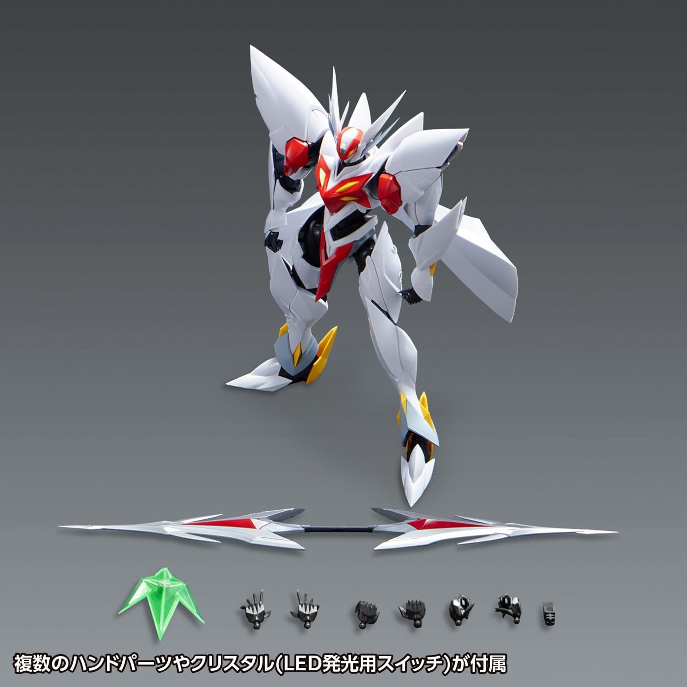
Figure 4.2: White parts with a glossy finish, designed for unpainted assembly.
4.3 Core Body Assembly
Follow the numerical sequence in the included diagrammatic instructions to assemble the core body, starting with the torso and head. Pay attention to the orientation of each part.
4.4 LED Unit Installation
The LED luminescent unit is integrated into specific parts of the model. Install two CR1220 batteries (sold separately) into the LED unit, observing correct polarity. The unit is activated by placing the crystal (LED light switch) into its designated slot.

Figure 4.3: LED luminescent unit in operation.
4.5 Articulation and Gimmick Assembly
Assemble the limbs and armor, noting the articulated joints and interactive armor gimmicks. The model features a wide range of motion for dynamic posing.
- Head and Torso Articulation: The head has a wide range of motion, allowing it to be deeply angled downwards. The abdominal parts are linked to the chest's movement, enhancing dynamic poses.

Figure 4.4: Head and torso articulation details.
- Shoulder Armor Movement: Sliding the shoulder armor upwards increases the range of motion for the arms. Moving the red parts of the shoulder armor also expands articulation.

Figure 4.5: Shoulder armor sliding mechanism.

Figure 4.6: Shoulder armor rotational movement.
- Leg and Ankle Articulation: Extending the ankle joints improves ground contact and stability for various poses.
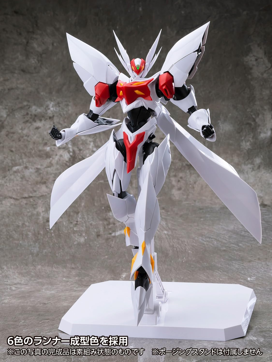
Figure 4.7: Leg and ankle articulation for stability.
4.6 Weapon Assembly
Assemble the Tech Lancer. It is designed to be held by the designated weapon-holding hand part.
5. Operating Instructions
5.1 Activating the LED Unit
To activate the LED luminescent unit, insert the crystal (LED light switch) into its designated slot on the model. The internal LEDs will illuminate. To simulate the Super Vorteca launch scene, remove and re-insert the crystal; the LEDs will begin to blink.
5.2 Posing the Model
Utilize the various articulation points and interactive armor gimmicks to achieve dynamic poses. Refer to the assembly section for details on specific joint movements.

Figure 5.1: Example of a dynamic action pose.

Figure 5.2: Rear-side view demonstrating articulation.

Figure 5.3: Example of a low-stance action pose.

Figure 5.4: Example of a dynamic mid-air pose.

Figure 5.5: Another dynamic action pose.
6. Maintenance
- Cleaning: Dust the model regularly with a soft, dry cloth or a soft brush. Do not use harsh chemicals or abrasive cleaners.
- Storage: Store the model in a cool, dry place away from direct sunlight and extreme temperatures to prevent material degradation or discoloration.
- Battery Replacement: If the LED unit's light dims or stops working, replace the CR1220 batteries. Ensure proper polarity.
- Joint Care: If joints become loose over time, a small amount of clear nail polish or hobby-grade joint tightener can be applied to the peg and allowed to dry before reassembly.
7. Troubleshooting
| Problem | Possible Cause | Solution |
|---|---|---|
| LED unit does not light up. | Batteries are dead or incorrectly inserted. Crystal switch not fully inserted. | Check battery polarity and replace batteries if necessary. Ensure the crystal switch is fully seated. |
| Parts do not fit together. | Excess plastic (nubs) remaining from runners. Incorrect part orientation. | Carefully trim any remaining nubs with a hobby knife or file. Refer to the instruction diagrams to confirm part orientation. |
| Joints are too loose. | Normal wear and tear. | Apply a thin coat of clear nail polish or hobby-grade joint tightener to the peg of the loose joint and allow it to dry completely before reassembling. |
| Model falls over easily. | Improper posing or unstable surface. Ankle joints not fully extended. | Adjust the pose to ensure balance. Place on a flat, stable surface. Extend ankle joints for better ground contact as shown in Figure 4.7. |
8. Specifications
| Feature | Detail |
|---|---|
| Model Name | Blaster Tekkaman Blade |
| Model Number | KM-127 |
| Brand | Wave |
| Scale | Non-scale |
| Completed Height | Approx. 8.7 inches (220 mm) |
| Material | ABS Plastic |
| Assembly Type | Snap-fit (no adhesives required) |
| Included Accessories | Tech Lancer, 3 types of hand parts, Crystal (LED light switch) |
| Special Features | LED Luminescent Unit (uses 2 CR1220 batteries, sold separately), Interactive Armor, Super Vorteca Launch Scene Simulation |
| Molding | 6 runner molded colors, partially painted parts, glossy white finish |
| Product Dimensions (L x W x H) | 8.66 x 3.94 x 3.94 inches |
| Item Weight | 2.31 pounds |
| Manufacturer | Tachibu Kogyo (ORANGE CAT INDUSTRY) / Wave Co., Ltd. (Import Seller) |
9. Warranty and Support
This product is manufactured with high-quality standards. Due to the nature of plastic model kits, individual parts are not typically covered by a direct warranty once assembly has begun. However, if you discover any missing or defective parts upon opening the package, please contact the retailer or the import seller, Wave Co., Ltd., with your proof of purchase. Please note that damage incurred during assembly or due to improper handling is not covered.
For further assistance or inquiries, please refer to the contact information provided by your point of purchase or the official Wave Co., Ltd. website.


