1. Introduction
This user manual provides comprehensive instructions for the installation, operation, and maintenance of the Temank MPPT 80A Solar Charge Controller. This advanced controller is designed to efficiently manage power flow from your solar panels to your battery bank, ensuring optimal charging and system longevity. It supports 12V, 24V, 36V, and 48V battery systems automatically and can be connected in parallel for increased capacity.
2. Key Features
- Maximum 12 Units in Parallel: Supports connecting up to 12 units in parallel to increase total solar system capacity and power output. Compatible with 100A MPPT controllers (Model: POW-M100-PRO) for parallel operation.
- Dual Cooling System: Features a die-cast aluminum construction for excellent heat dissipation and a turbofan fan (activates >45°C, turns off <40°C) for efficient and quiet cooling.
- Multi-Battery Compatibility: Compatible with 12V/24V/36V/48V lead-acid (Sealed, Gel, Flooded) and lithium (LiFePO4, Lithium-Ion) batteries. User-programmable charging parameters available.
- Wide Voltage/Power Support: Supports high PV input power and voltage. For a 12V system, suggested solar power is 960W with a PV input voltage range of DC20V~DC80V. Higher power and voltage support for 24V, 36V, and 48V systems.
- Enhanced Protection: Provides comprehensive protection against overcurrent, short circuit, reversed polarity, overvoltage, over-discharge, and over-temperature. Includes an external temperature probe for precise battery temperature monitoring.
- 99% Tracking Technology: Utilizes advanced Maximum Power Point Tracking (MPPT) technology with a tracking efficiency of not less than 99% and a peak conversion efficiency up to 97%.
3. Safety Information
Please read and understand all safety instructions before installing or operating the solar charge controller. Failure to follow these instructions may result in electric shock, fire, or serious injury.
- Ensure all connections are secure and correct before applying power.
- Always disconnect the solar panels and battery before performing any maintenance or wiring.
- Do not charge lithium batteries when the ambient temperature is below 0°C (32°F) to prevent damage to the battery.
- Install the controller in a well-ventilated area, away from flammable materials and direct sunlight.
- The controller is designed for indoor use or in a protective enclosure. Avoid exposure to water or excessive humidity.
- Only qualified personnel should perform installation and maintenance.
- Ensure proper grounding of the system. The controller features a negative grounding design for safety.
4. Product Overview and Components
The Temank MPPT 80A Solar Charge Controller features a robust design with an intuitive display and essential connection ports.

Figure 4.1: Temank MPPT 80A Solar Charge Controller with included accessories. This image displays the main unit, connection terminals, and the external temperature probe.
4.1. LCD Display and Control Buttons
The controller is equipped with a backlit LCD screen for easy monitoring of system parameters and three control buttons for navigation and settings adjustment.
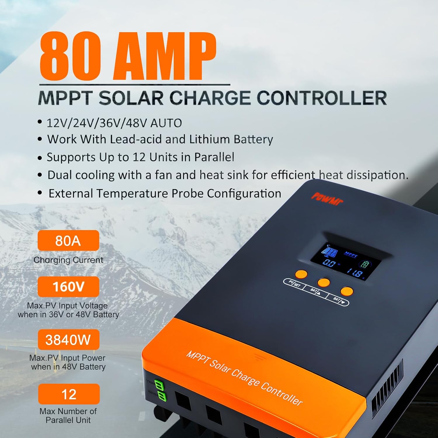
Figure 4.2: Detailed view of the LCD screen and control buttons.
- LCD Display Screen:
- Day/Night Indicator
- Battery Capacity
- Charging in Progress
- PV Parameter (Voltage, Current, Power)
- Battery Parameter (Voltage, Current, Temperature)
- Control Buttons:
- PV/SET: Used to browse PV parameters and enter/confirm settings.
- BAT/▲: Used to browse battery parameters and increase values.
- BAT/▼: Used to browse battery parameters and decrease values.
4.2. Connection Ports
- Battery Interface: Connects to the battery bank.
- PV Input Interface: Connects to the solar panel array.
- Temperature Probe Port: For connecting the external temperature sensor to ensure accurate battery charging.
- Parallel Communication Port: Used for connecting multiple controllers in parallel.
5. Setup and Installation
Proper installation is crucial for the safe and efficient operation of your solar power system. Follow these steps carefully.
5.1. Wiring Sequence
Always connect components in the following order to prevent damage:
- Connect the Battery: Connect the battery bank to the controller's battery terminals. Ensure correct polarity (positive to positive, negative to negative). The controller will automatically detect the battery voltage (12V/24V/36V/48V).
- Connect the Solar Panels: Connect the solar panel array to the controller's PV input terminals. Ensure correct polarity. The controller will begin charging the battery.
- Connect the Load (Optional): If your system includes a DC load directly connected to the controller, connect it to the load terminals.

Figure 5.1: General Solar Connect Diagram. This diagram illustrates the proper connection sequence for the solar charge controller within a solar power system.
5.2. Parallel Connection (Up to 12 Units)
The Temank MPPT 80A controller supports parallel connection of up to 12 units to expand your solar system's capacity. When paralleling, ensure:
- Communication between controllers is achieved through communication lines connected to the parallel communication ports.
- Each controller must be connected to a separate solar array.
- All parallel controllers are connected to the same battery bank.

Figure 5.2: Parallel Operation Schematic. This diagram shows how multiple MPPT controllers can be connected in parallel to a single battery bank, each with its own solar array.
5.3. Solar Panel Input Requirements
Ensure your solar panel array meets the following specifications for optimal performance:
| System Voltage | Maximum Input Power (80A Model) | PV Input Voltage Range |
|---|---|---|
| For 12V System | 960W | DC20V~DC80V |
| For 24V System | 1920W | DC37V~DC105V |
| For 36V System | 2880W | DC50V~DC160V |
| For 48V System | 3840W | DC72V~DC160V |
The maximum PV array open circuit voltage is 160VDC.
6. Operating Instructions
Once installed, the controller will automatically begin charging. Use the LCD display and buttons to monitor and adjust settings.
6.1. Monitoring System Status
Press the "PV/SET" and "BAT/▲" / "BAT/▼" buttons to cycle through various display screens showing real-time system data, including:
- Current Battery Voltage
- Charging Current
- Device Temperature
- Battery Type Setting
- Parallel Communication Code
- Calibrated Battery Voltage
- Boost Charging Voltage
- Float Charging Voltage
- MPPT Tracking Return Voltage
6.2. Battery Type and Charging Parameters
The controller supports various battery types with pre-set charging parameters. You can also customize parameters for specific battery needs.

Figure 6.1: Battery Compatibility and Settings. This image shows the controller's compatibility with Sealed, Gel, Flooded, and Lithium batteries, along with a table of display codes for different battery types.
To change battery type or customize parameters:
- Press and hold the "PV/SET" button for 5 seconds to enter the setting mode.
- Use the "BAT/▲" and "BAT/▼" buttons to navigate through the parameters.
- Press "PV/SET" to select a parameter, then use "BAT/▲" and "BAT/▼" to adjust the value.
- Press "PV/SET" again to confirm the setting.
- Exit setting mode by pressing and holding "PV/SET" or waiting for automatic timeout.
User programmable parameters include Absorption Voltage, Float Voltage, Low Voltage Cutoff, and Load Timer.
6.3. Smart 3-Stage Charging
The controller employs a smart 3-stage charging algorithm to optimize battery health and lifespan:
- Bulk Charge: Charges the battery at maximum current until it reaches the absorption voltage.
- Absorption Charge: Maintains a constant voltage while the current gradually decreases, ensuring the battery is fully charged.
- Float Charge: Reduces the voltage to a lower level to maintain the battery at full charge, compensating for self-discharge.

Figure 6.2: Efficient 3-Stage Charging. This graphic illustrates the three stages of battery charging for optimal performance.
7. Maintenance
Regular maintenance ensures the longevity and optimal performance of your solar charge controller.
- Inspect Connections: Periodically check all wiring connections for tightness and corrosion. Loose connections can cause overheating and poor performance.
- Clean the Controller: Keep the controller clean and free from dust and debris. Use a dry cloth to wipe the exterior. Ensure ventilation openings are not blocked.
- Monitor Fan Operation: The internal turbofan activates when the temperature exceeds 45°C and turns off below 40°C. Ensure the fan operates freely and is not obstructed.
- Check Battery Health: Regularly monitor your battery bank's voltage and overall health. Refer to your battery manufacturer's guidelines for specific maintenance.
- Environmental Conditions: Ensure the installation environment remains within the recommended temperature and humidity ranges.

Figure 7.1: Dual Cooling System. This image highlights the efficient heat dissipation design, including the intelligent fan, which is crucial for maintenance checks.
8. Troubleshooting
This section addresses common issues you might encounter with your solar charge controller.
8.1. Common Issues and Solutions
- No Display/Controller Not Powering On:
- Check battery connections and ensure they are secure and have sufficient voltage.
- Verify battery polarity.
- Ensure the battery fuse (if installed) is not blown.
- No Charging/Low Charging Current:
- Check solar panel connections and polarity.
- Verify solar panel voltage is within the controller's operating range (refer to Table 5.1).
- Ensure there is sufficient sunlight.
- Check for shading on solar panels. Partial shading can significantly reduce power output.
- Verify the battery type setting matches your battery.
- Over-temperature Warning:
- Ensure the controller is installed in a well-ventilated area.
- Check that the cooling fan is operating correctly and not obstructed.
- Clean any dust or debris from the heat sink fins.
- Error Codes on Display:
- Refer to the specific error code in the full product manual (if available) or contact customer support.
8.2. Built-in Protections
The controller is equipped with multiple protection features to safeguard your system:
- Overcurrent Protection
- Short Circuit Protection
- Reversed Polarity Protection (PV and Battery)
- Overvoltage Protection
- Over-discharge Protection
- Over-temperature Protection
9. Specifications
Key technical specifications for the Temank MPPT 80A Solar Charge Controller:
| Specification | Value |
|---|---|
| Model | MPPT 80A-Parallel |
| Brand | Temank |
| System Voltage | 12V/24V/36V/48V Auto |
| Rated Charge Current | 80A |
| Max. PV Input Voltage | 160VDC |
| Max. PV Input Power (12V System) | 960W |
| Max. PV Input Power (24V System) | 1920W |
| Max. PV Input Power (36V System) | 2880W |
| Max. PV Input Power (48V System) | 3840W |
| Tracking Efficiency | ≥99% |
| Peak Conversion Efficiency | Up to 97% |
| Battery Types Supported | Lead-Acid (Sealed, Gel, Flooded), Lithium (LiFePO4, Lithium-Ion), User-Defined |
| Display Type | LCD |
| Cooling Method | Die-cast aluminum heat sink + Turbofan |
| Parallel Connection | Up to 12 units |
| Item Weight | 5.5 pounds |
| Package Dimensions | 12.4 x 9.33 x 4.61 inches |
10. Warranty and Support
For warranty information and technical support, please refer to the documentation included with your product packaging or contact Temank customer service directly. Details regarding warranty periods and claims procedures are typically provided by the manufacturer or the authorized seller.
For further assistance, you may visit the official Temank store or contact their support channels.
Brand: Temank