
1. Introduction
The TIDRADIO TD-805S is a compact dual-band VHF/UHF short antenna designed for ham radio use. This antenna features an enhanced design for improved signal stability and reception, making it a practical accessory for various portable radio applications.
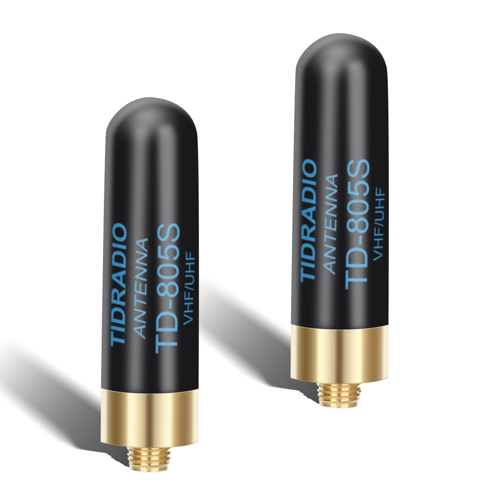
Image: The TIDRADIO TD-805S Short Antenna connected to a handheld ham radio.
2. Key Features
- Enhanced Version TD-805S: Incorporates new components for improved stability and signal quality. Features a specially-tuned loading coil to reduce interference, boost signal, and widen the receiving range.
- Compact Size: Smaller than many other short antennas, ensuring portability and reducing physical interference during use.
- Dual Band Frequency: Supports 144/430MHz (136-174MHz + 400-470MHz) for versatile ham radio operation.
- Gain (MAX): 2.15dBi/3.0dBi.
- Connector Type: SMA-Female.
- Length: Approximately 5 CM (1.96 Inch).
- Max Power Handling: 12W.
- Impedance: 50 OHM.
- Application: Primarily designed for ham radio use. Note that GMRS frequencies may exhibit reduced performance due to being off-center band.

Image: Key specifications of the TD-805S antenna.

Image: Internal view of the antenna's loading coil, designed to enhance signal.
3. Setup and Installation
Follow these steps to properly install your TD-805S short antenna:
- Identify the Antenna Port: Locate the SMA-Female antenna port on your compatible ham radio. This is typically a threaded connector on the top of the radio.
- Align the Connector: Carefully align the SMA-Male connector of the TD-805S antenna with the radio's antenna port. Ensure the threads are properly aligned to prevent cross-threading.
- Screw On: Gently screw the antenna onto the port clockwise until it is finger-tight. Do not overtighten, as excessive force can damage the antenna connector or the radio's port.
- Verify Connection: Ensure the antenna is securely attached and stable before operating the radio. A loose connection can result in poor performance or damage.

Image: The compact 1.96-inch length of the TD-805S antenna.
4. Operation Guidelines
To ensure optimal performance and longevity of your TD-805S antenna, consider the following:
- Optimal Placement: For best signal reception and transmission, operate your radio in an open area with minimal obstructions such as buildings, dense foliage, or large metal structures.
- Power Limits: Do not exceed the maximum power rating of 12W. Transmitting above this limit can cause damage to the antenna and potentially your radio.
- Frequency Use: This antenna is specifically optimized for the 144/430MHz (VHF/UHF) ham radio bands. While it may function on other frequencies, performance may vary. For GMRS frequencies, performance might be below expectations as they are not centered on the antenna's optimal band.
- Short-Range Communication: Due to its compact size, the TD-805S antenna is ideal for short to medium-range communications where portability and discretion are important. For extended long-range communication, a longer, higher-gain antenna may be more suitable.

Image: The TD-805S antenna's suitability for multi-scenario applications due to its pocket size.
5. Compatible Radios
The TIDRADIO TD-805S antenna is designed for compatibility with most ham radios that feature an SMA-Female antenna connector. This includes, but is not limited to, the following models:
- BAOFENG UV5R mini
- BAOFENG AR-5RM
- BAOFENG 5RM
- BAOFENG BF-F8HP Pro
- BAOFENG K5 Plus
- BAOFENG K5
- TIDRADIO TD-H8
- TIDRADIO TD-H3 Plus
- TIDRADIO 5RH Pro
- BAOFENG UV32
- BAOFENG DM32
- BAOFENG K5Plus
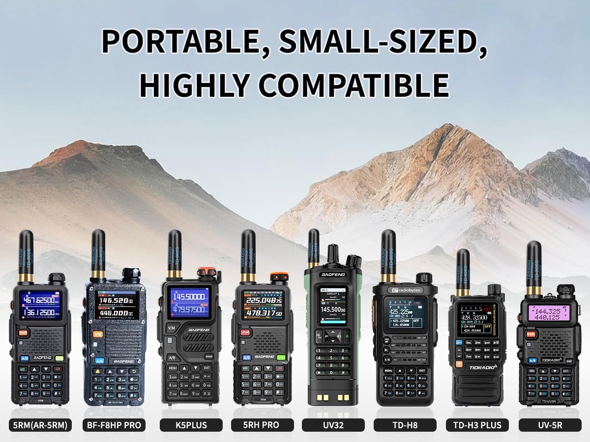
Image: Examples of portable radios compatible with the TD-805S antenna.
6. Technical Specifications
| Feature | Detail |
|---|---|
| Frequency | 144/430MHz (136-174MHz + 400-470MHz) |
| Gain (MAX) | 2.15dBi/3.0dBi |
| Connector | SMA-Female |
| Length | 5 CM (1.96 Inch) |
| Max Power | 12W |
| Impedance | 50 OHM |
| Brand | TIDRADIO |
| Model | TD-805S |
| Color | Black |
| Number of Items | 2 (for the 2-pack variant) |
7. Maintenance
Proper maintenance ensures the longevity and performance of your antenna:
- Cleaning: Wipe the antenna with a soft, dry cloth to remove dust, dirt, or moisture. Avoid using harsh chemicals, solvents, or abrasive cleaners, as these can damage the antenna's finish or materials.
- Storage: When not in use, store the antenna in a cool, dry place away from direct sunlight and extreme temperatures. Protect the connector from dust and physical damage.
- Inspection: Periodically inspect the antenna and its connector for any signs of wear, corrosion, or physical damage. Ensure the connector threads are clean and free of debris.
8. Troubleshooting
If you encounter issues with your TD-805S antenna, consider the following troubleshooting steps:
- Poor Signal Reception/Transmission:
- Ensure the antenna is securely and correctly attached to the radio's SMA-Female port.
- Verify that your radio is set to the correct frequency band (VHF or UHF) that the antenna is designed for.
- Move to an open area with fewer physical obstructions that might block radio signals.
- Remember that short antennas have inherent limitations in range compared to longer, higher-gain antennas.
- Antenna Not Fitting Securely:
- Confirm that your radio has an SMA-Female connector. The TD-805S uses an SMA-Male connector.
- Do not force the connection, as this can damage the threads on either the antenna or the radio.
- High SWR (Standing Wave Ratio):
- High SWR indicates a mismatch between the antenna and the radio, which can reduce performance and potentially damage the radio's final amplifier.
- While the antenna is designed for specific bands, environmental factors or specific radio models might show higher SWR.
- If you have access to an SWR meter, test the antenna's performance on your specific radio and desired operating frequencies.
- Note that performance on GMRS frequencies may be below expectations, potentially leading to higher SWR, as these frequencies are not at the antenna's center band.
9. Warranty and Support
For detailed warranty information, product support, or to address any technical inquiries not covered in this manual, please refer to the official TIDRADIO website. You can also contact TIDRADIO customer service directly through the contact information provided on their website. Please retain your purchase receipt as proof of purchase for any warranty claims.


