1. Introduction
The Y&H 140A MPPT Solar Charge Controller is an advanced device designed for efficient energy harvesting from solar panels. It utilizes Maximum Power Point Tracking (MPPT) technology to optimize power output and charging efficiency for 48V battery systems. This controller supports high PV input voltages up to 500V, making it suitable for large-scale solar power generation systems in various applications, including residential, commercial, and off-grid setups.
This manual provides essential information for the safe installation, operation, and maintenance of your solar charge controller. Please read it thoroughly before installation and use.
2. Safety Information
WARNING: Failure to follow these safety instructions may result in serious injury or death, and may damage the controller or other equipment.
- Ensure all connections are secure and correct before applying power.
- Always disconnect the solar array and battery power before installing or servicing the controller.
- Use appropriate tools and personal protective equipment (PPE) during installation.
- The controller generates high voltage. Only qualified personnel should perform installation and maintenance.
- Do not disassemble or attempt to repair the controller yourself. Contact qualified service personnel.
- Ensure proper ventilation around the controller to prevent overheating.
- This controller is designed for 48V battery systems. Do not connect to other voltage systems.
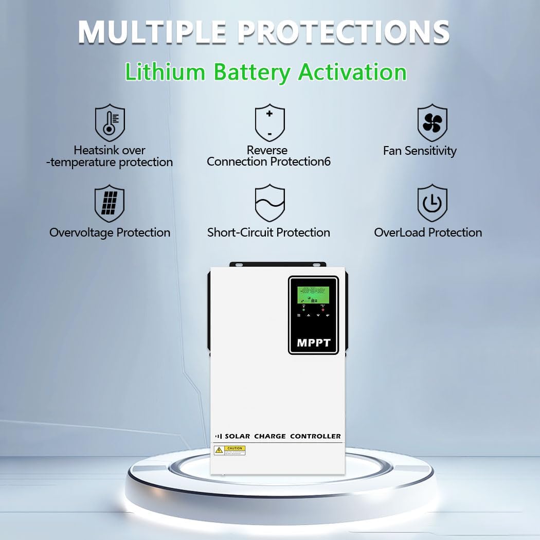
Figure 2.1: Multiple Protection Features. The controller includes heatsink over-temperature protection, reverse connection protection, fan sensitivity, overvoltage protection, short-circuit protection, and overload protection to ensure system stability and safety.
3. Product Overview
3.1 Key Features
- Maximum Power Point Tracking (MPPT) technology for up to 98% tracking efficiency and 99% conversion efficiency.
- Wide PV input voltage range: 60-500 VDC.
- Intelligent 4-stage battery charging design (Bulk, Constant, Float, Equalize) to optimize battery lifespan.
- Comprehensive protection: overcharge, over-discharge, short-circuit, PV overvoltage, overcurrent, and overheating.
- LCD display and user-friendly interface for system monitoring and configuration.
- Dual fans for efficient heat dissipation.
- Compatible with various 48V battery types: AMG, USE, FLD, LiFePO4, and user-defined batteries.
- Supports high voltage DC (HVDC) transmission to reduce line loss and improve efficiency.
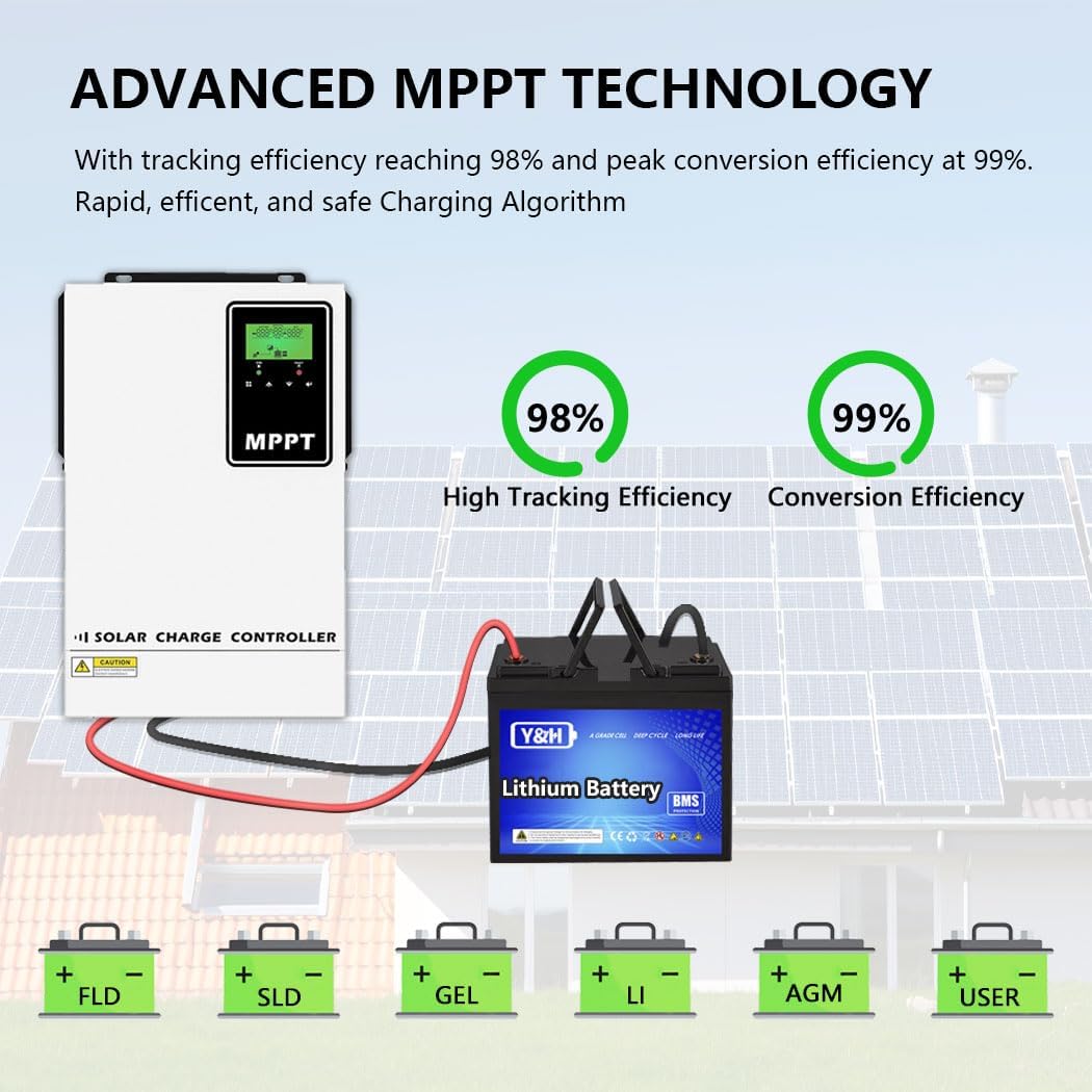
Figure 3.1: Advanced MPPT Technology. This image highlights the high tracking efficiency (98%) and conversion efficiency (99%) of the controller, along with its compatibility with various battery types like FLD, SLD, GEL, LI, AGM, and user-defined.
3.2 Component Identification

Figure 3.2: Port Introduction. This diagram identifies the key components and ports of the controller:
- LCD display
- Fault indicator
- Charging indicator
- Function buttons
- PV input terminals
- Ground connection
- Battery input terminals
- Anti-dust kit (if included)
4. Setup and Installation
4.1 Mounting the Controller
Mount the controller vertically on a non-flammable surface in a well-ventilated area. Ensure there is sufficient clearance around the unit for proper airflow and heat dissipation. Avoid direct sunlight, high temperatures, and moisture.
4.2 Wiring Connections
IMPORTANT: Always connect the battery first, then the solar array. Disconnect in reverse order (solar array first, then battery).
- Battery Connection: Connect the battery cables to the battery input terminals (7) on the controller. Ensure correct polarity (+ to + and - to -). The recommended battery cable size for 48V/140A is 1 x 2 AWG (25mm²), with a maximum torque value of 2 Nm.
- Solar Panel Connection: Connect the solar panel array cables to the PV input terminals (5). Ensure correct polarity. The recommended PV cable size for 48V/140A is 1 x 12 AWG (4mm²), with a maximum torque value of 1.2 Nm. The maximum open circuit voltage of the PV array should not exceed 500V. The optimal recommended operating voltage is 280V.
- Ground Connection: Connect the ground wire to the ground connection terminal (6).
WARNING: Using improper cable connections or sizes is critical to the safe and efficient operation of the system. Refer to the specifications for recommended cable sizes.

Figure 4.1: Easy Connections Diagram. This illustration shows the typical wiring setup for the solar charge controller, connecting solar panels, a 48V battery bank, and an inverter to power AC loads.
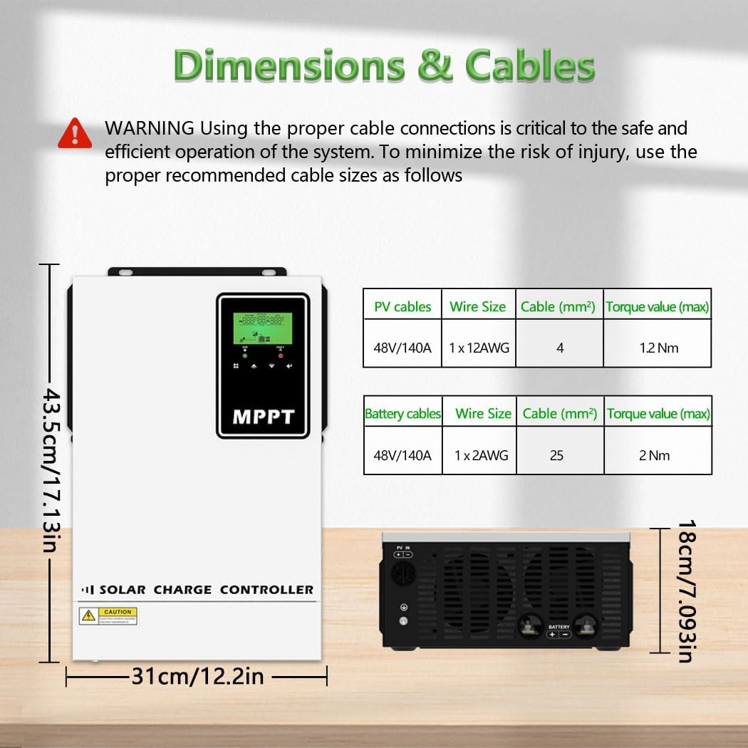
Figure 4.2: Dimensions and Cable Specifications. This image provides the physical dimensions of the controller and a table detailing recommended wire sizes and torque values for PV and battery connections.
5. Operating Instructions
5.1 LCD Display and Interface
The LCD display (1) provides real-time information about the system's performance. Use the function buttons (4) to navigate through the display menus and configure settings. The display typically shows:
- PV voltage and current
- PV power output
- Battery voltage and charging current
- System date and time
- Energy generation capacity
- Error codes (if any)
- Software version number
The fault indicator (2) illuminates to signal system errors, while the charging indicator (3) shows the current charging status.
5.2 Battery Type Configuration
The controller is compatible with various 48V battery types. It is crucial to select the correct battery type in the controller settings to ensure optimal charging and prolong battery life. Supported types include:
- AMG (Absorbed Glass Mat)
- USE (User-defined, likely for custom lead-acid settings)
- FLD (Flooded Lead-Acid)
- LiFePO4 (Lithium Iron Phosphate)
- User-defined (allows for custom charging parameters for specific battery chemistries)
Refer to your battery manufacturer's specifications for recommended charging parameters and configure the controller accordingly, especially for user-defined battery types.
5.3 MPPT Charging Mode
The controller employs a 4-stage charging algorithm to efficiently and safely charge your batteries, extending their lifespan:

Figure 5.1: 4-Stage Charging Process. This graph shows the battery voltage and charging stages over time, including Bulk Charge, Constant Charging, and Float Charge, with an Equalize Boost phase to reverse sulfation and improve battery capacity.
- Bulk Charge (A): This is the initial stage where the battery is charged at its maximum current until the voltage reaches a set level.
- Constant Charging (B): The voltage is held constant while the current gradually decreases.
- Float Charge (C): Once the battery is fully charged, the voltage is reduced to a lower "float" level to maintain a full charge without overcharging.
- Equalize Boost: Periodically, or as needed, the controller may apply an equalization charge to flooded lead-acid batteries. This involves charging at a higher voltage to balance cell voltages and prevent sulfation, which can reduce battery capacity.
6. Maintenance
Regular maintenance ensures the longevity and optimal performance of your solar charge controller:
- Visual Inspection: Periodically check for any loose connections, damaged wiring, or signs of corrosion.
- Cleaning: Keep the controller clean and free from dust and debris. Ensure the ventilation openings are not blocked. Use a dry cloth for cleaning.
- Fan Check: Ensure the cooling fans are operating correctly and are not obstructed.
- Firmware Updates: Check the manufacturer's website for any available firmware updates.
- Battery Inspection: Regularly inspect your batteries for signs of damage, leakage, or swelling. Ensure battery terminals are clean and tight.
7. Troubleshooting
If you encounter issues with your Y&H 140A MPPT Solar Charge Controller, refer to the following common troubleshooting steps:
| Problem | Possible Cause | Solution |
|---|---|---|
| No display/No power | Loose battery connection, battery voltage too low, fuse blown. | Check battery connections and voltage. Ensure battery voltage is above the minimum operating threshold. Check and replace fuses if necessary. |
| No charging from PV | PV array disconnected, PV voltage too low/high, shading on panels, fault indicator active. | Check PV connections and ensure correct polarity. Verify PV voltage is within the 60-500VDC operating range. Clear any shading. Check LCD for error codes. |
| Battery not fully charged | Incorrect battery type setting, insufficient PV power, battery degradation. | Verify battery type setting matches your battery. Ensure PV array size is adequate for your load and battery capacity. Test battery health. |
| Overheating | Poor ventilation, blocked fans, excessive ambient temperature. | Ensure adequate clearance around the controller. Clean fan vents. Relocate controller to a cooler environment if possible. |
| Error code displayed | Specific system fault. | Refer to the controller's internal manual or manufacturer's support for specific error code definitions and solutions. |
For persistent issues or error codes not listed, please contact Y&H customer support.
8. Specifications
| Feature | Specification |
|---|---|
| Model Number | XMC-140A-48V-UK |
| System Voltage | 48 VDC |
| Max PV Open Circuit Voltage (Voc) | 500 V |
| PV Start-up Voltage | 90 V |
| Recommended Optimal PV Operating Voltage | 280 V |
| Max PV Array Power | 6500 W |
| Charging Current | 140 A |
| PV Cable Size (Recommended) | 1 x 12 AWG (4mm²) |
| Battery Cable Size (Recommended) | 1 x 2 AWG (25mm²) |
| Dimensions (L x W x H) | 43 x 31 x 18 cm (17.13 x 12.2 x 7.093 inches) |
| Weight | 6.4 kg |
| Display Type | LCD |
| Compatible Battery Types | AMG, USE, FLD, LiFePO4, User-defined |
9. Warranty and Support
For warranty information, please refer to the documentation included with your purchase or visit the official Y&H website. If you require technical assistance, troubleshooting support, or have questions regarding your Y&H 140A MPPT Solar Charge Controller, please contact Y&H customer service through their official channels.
Please have your model number (XMC-140A-48V-UK) and purchase details ready when contacting support.


