1. Introduction
Welcome to the MokerLink IP67 Outdoor 5 Port Gigabit PoE Extender user manual. This document provides essential information for the proper installation, operation, and maintenance of your device. Please read this manual thoroughly before use to ensure optimal performance and safety.
2. Product Overview
2.1 Key Features
- 5 Gigabit PoE Ports: Includes 1 PoE In and 4 PoE Out, supporting 10/100/1000Mbps speeds. Compatible with 100BASE-TX (Cat5 or later UTP up to 150 meters) and 1000BASE-TX (Cat6 or later UTP up to 100 meters).
- IP67 Outdoor Weatherproof: Features a rugged industrial-grade metal housing with protected cable interfaces and waterproof caps. Designed for outdoor and indoor environments such as warehouses, computer rooms, garages, and attics, offering superior waterproof, dustproof, and snowproof protection.
- IEEE 802.3 af/at/bt Compliance: All ports support this standard PoE. Input supports up to 120W (IEEE802.3af/at/bt). Output 1 supports up to 90W (IEEE802.3af/at/bt), and Outputs 2-4 support up to 30W each (IEEE802.3af/at). PoE Voltage is 44-57 Vdc. PoE pin assignments: Input/Out1: 1/2 (+), 4/5 (+), 3/6 (-), 7/8 (-); Out2-4: 1/2 (+), 3/6 (-).
- Unmanaged Plug & Play: Features automatic device detection and requires no configuration. Simply connect Ethernet cables. Includes PoE Dog functionality for automatic fault device reset.
- Easy Installation: No external power adapter is required when powered by PoE. Supports optional DC 44-57V Max 180W power input via a Phoenix terminal connector. The metal case supports wall mounting. Supports 3-level cascading to extend PoE coverage.
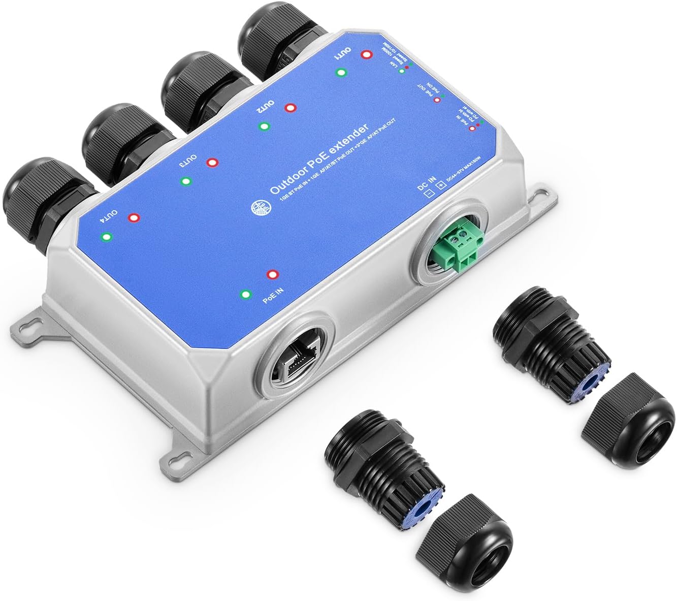
2.2 Product Components
3. Safety Information
- Ensure proper grounding for all connected equipment.
- Do not expose the device to extreme temperatures outside its operating range (-20°C to +75°C).
- Always pass the network cable through the waterproof cap before making the RJ45 connection to ensure IP67 rating.
- Disconnect power before performing any maintenance or installation.
- Avoid placing the device in areas with high humidity or direct water exposure unless all waterproof caps are securely sealed.
4. Setup
4.1 Package Contents
- MokerLink IP67 Outdoor 5 Port Gigabit PoE Extender
- Waterproof caps for RJ45 ports
- Phoenix terminal connector (for optional DC power input)
4.2 Physical Installation
The extender is designed for wall mounting. Use appropriate screws and anchors (not included) for your mounting surface. Ensure the mounting location is stable and provides adequate ventilation, even though the device is weatherproof.

4.3 Connecting Network Cables
- Unscrew the waterproof cap components (nut, rubber gasket, and main body).
- Thread the Ethernet cable through the cap's outer nut and then the rubber gasket.
- Crimp an RJ45 connector onto the cable end.
- Insert the RJ45 connector into the desired port (PoE In or PoE Out).
- Screw the waterproof cap components back together tightly around the cable to ensure a sealed connection.
- Repeat for all necessary ports. Use provided flat caps for any unused ports to maintain the IP67 rating.
Important: Ensure the network cable is passed through the waterproof cap before making the RJ45 connection to maintain the IP67 rating.

4.4 Powering the Device
The extender can be powered in two ways:
- PoE Input: Connect a PoE-enabled switch or injector to the "PoE IN" port. The device will draw power from this connection, eliminating the need for a separate power adapter.
- DC Input: For non-PoE input scenarios or when additional power is required, connect a DC 44-57V (Max 180W) power supply to the Phoenix terminal connector. Ensure correct polarity.

5. Operation
5.1 LED Indicators
The device features LED indicators to show status:
- PoE Out Indicator: Green (Link normal), Off (Link blocked).
- PoE In Indicator: Green (PD with af/at), Red (PD with bt).
- LAN Indicator: Green (10/100Mbps), Red (1000Mbps).
5.2 PoE Dog Function
The integrated PoE Dog function automatically detects and resets connected PoE devices that become unresponsive, ensuring continuous operation without manual intervention.
5.3 Cascading Multiple Extenders
The MokerLink PoE Extender supports up to 3 levels of cascading, allowing for extended PoE transmission distances up to 1000ft (300m). Each extender adds up to 100 meters of range to the network and power delivery.

6. Maintenance
- Regularly inspect all cable connections for tightness and integrity, especially in outdoor environments.
- Keep the device free from excessive dust and debris. Use a soft, dry cloth for cleaning. Do not use liquid cleaners.
- Ensure waterproof caps are securely fastened at all times to prevent moisture ingress, which can damage the device.
- Periodically check for firmware updates on the MokerLink official website, if applicable for your model.
7. Troubleshooting
7.1 No Power to Connected Devices
- Check the "PoE In" LED. If off, ensure the upstream PoE source is active and providing power.
- Verify the power budget. Ensure the total power draw of connected devices does not exceed the extender's output capacity (90W for Out1, 30W for Out2-4).
- If using DC input, ensure the power supply is correctly connected and within the 44-57V range with correct polarity.
- Inspect all Ethernet cables for damage or improper connection.
7.2 No Network Link
- Check the "LAN Indicator" for the respective port. If off or red when it should be green, inspect the Ethernet cable for damage or improper crimping.
- Ensure the connected device (e.g., IP camera) is functioning correctly and powered on.
- Verify RJ45 connections are secure and properly seated in the ports.
7.3 Intermittent Connection
- Check for loose cable connections or damaged cables. Replace any suspect cables.
- Ensure the waterproof caps are fully tightened to prevent environmental interference (moisture, dust).
- Verify that the operating temperature is within the specified range (-20°C to +75°C). Extreme temperatures can affect performance.
8. Specifications
| Feature | Detail |
|---|---|
| Model | IP67 5 Port |
| Ports | 1 PoE In, 4 PoE Out (Gigabit) |
| Data Transfer Rate | 10/100/1000Mbps |
| PoE Standard | IEEE 802.3 af/at/bt |
| PoE Input | Max 120W (IEEE802.3af/at/bt) |
| PoE Output 1 | Max 90W (IEEE802.3af/at/bt) |
| PoE Output 2-4 | Max 30W (IEEE802.3af/at) |
| DC Input | 44-57V, Max 180W |
| Enclosure | IP67 Outdoor Weatherproof Metal |
| Operating Temperature | -20°C to +75°C |
| Dimensions | 145 x 77 x 43 mm (approx.) |
| Item Weight | 1.26 pounds |
| Manufacturer | MokerLink |
| Compatible Devices | IP Cameras, Routers |
9. Warranty and Support
For warranty information and technical support, please contact MokerLink customer service. Refer to the product packaging or the official MokerLink website for contact details. Keep your purchase receipt for warranty claims.
For additional resources and product information, you may visit the official MokerLink store:


