DALY Smart BMS 16S 48V 300A User Manual
Model: 16S 48V 300A
1. Introduction
The DALY Smart BMS (Battery Management System) 16S 48V 300A is an advanced protection board designed for LiFePO4 lithium battery packs. It integrates essential safety features with smart monitoring capabilities, ensuring the longevity and optimal performance of your battery system. This manual provides detailed instructions for proper installation, operation, and maintenance.
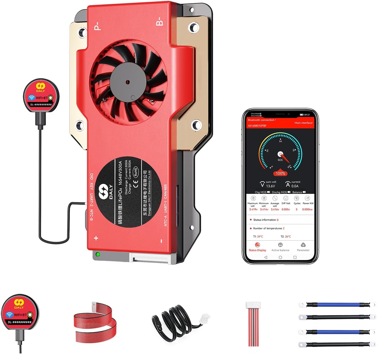
Image 1.1: DALY Smart BMS 16S 48V 300A and its accompanying components, including the Wi-Fi/Bluetooth module, sampling cable, and output lines.
2. Product Features
- Enhanced Battery Safety: Provides comprehensive protection against overcharging, over-discharging, overcurrent, short circuits, and extreme temperatures, safeguarding the battery pack.
- 2-in-1 Bluetooth/Wi-Fi Dongle: Enables remote monitoring and parameter adjustment via a mobile app (Bluetooth) or PC software (Wi-Fi, requires router connection).
- Strong Overcurrent Capability: Utilizes high-performance MOSFETs and TVS diodes to manage regenerative currents, preventing power-off issues in applications like golf carts.
- Multiple Interface Functions: Supports dual UART communication, compatible with BT&WIFI modules and touch displays. Features a Bluetooth activation-free function for easy wake-up via the app.

Image 2.1: Overview of the DALY Smart BMS's advanced features and design.
3. Specifications
The following table details the technical specifications for the DALY Smart BMS 16S 48V 300A.
| Specification | Value |
|---|---|
| Product Type | LiFePO4 16S 300A common port with balance |
| Discharge Current | 300A |
| Overdischarge Current | 450±9A |
| Charging Current | 300A |
| Overcharge Current | 450±9A |
| Overcharge Voltage | 3.75V±0.05V (Can be set) |
| Overdischarge Voltage | 2.2V±0.05V (Can be set) |
| Charge Voltage | 58.4V |
| Model | R24S (11~24S) |
| Dimensions (L x W x H) | 183 x 108 x 26 mm (7.2 x 4.25 x 1.02 inches) |
| Output Wire | 4AWG*2/200mm |
| Cable | 24AWG/450mm |
| Item Weight | 2.7 pounds (approx. 600-700g) |
| Operating Temperature | Charging: -35~75°C, Discharging: -35~75°C (Can be set) |
| Storage Temperature | -40~85°C |
| Working Current | < 20mA |
| Resting Current | < 600uA |
| Sleep Time | 3600s |

Image 3.1: Visual representation of the DALY Smart BMS specifications.
4. Installation and Wiring
Proper installation is crucial for the safe and effective operation of your DALY Smart BMS. Follow these steps carefully:
- Step 1: Solder the sampling cables. The first black cable in the sampling cable set connects to the negative terminal of the battery (B-). The second cable (red) connects to the positive terminal of the first string of batteries. Continue this pattern for all subsequent cables until all strings are connected.
- Step 2: Check the cables. After connecting the cables, use a multimeter to measure the voltage between two adjacent cables starting from the header. Ensure there are no incorrect connections or missing connections.
- Step 3: Connect the output wires. Connect the B- wire of the BMS to the total negative terminal of the battery pack. Then, plug the sampling cable to the BMS. After activating the BMS, verify that the voltage (battery voltage) between B+ & B- and the voltage between P+ & P- are consistent.

Image 4.1: Detailed wiring diagram for connecting the DALY Smart BMS to a battery pack, load, and charger.
5. Operating Instructions
5.1 Mobile App and PC Software Monitoring
The DALY Smart BMS can be monitored and configured using a dedicated mobile application or PC software. The included 2-in-1 Bluetooth/Wi-Fi dongle facilitates this connectivity.
- Bluetooth Connection: For local monitoring, connect the dongle to the BMS and pair it with your mobile device via Bluetooth. Open the DALY app to view real-time battery status and adjust parameters. The BMS supports a Bluetooth activation-free function, allowing direct wake-up via the app.
- Wi-Fi Connection: For long-distance control and monitoring, connect the dongle to a Wi-Fi router. This enables remote access to battery data and settings through the mobile app or PC software from any location with internet access.

Image 5.1: The DALY Smart BMS mobile application interface for monitoring battery parameters.
5.2 Video Demonstration
Watch this official video for a visual overview of the DALY S-series Smart BMS features and capabilities.
Video 5.2: An official DALY video showcasing the features and comprehensive upgrade of the S-series Smart BMS, highlighting its professional resistance to high current.
6. Maintenance and Best Practices
To ensure the longevity and optimal performance of your LiFePO4 battery pack and DALY Smart BMS, adhere to the following maintenance guidelines:
- Regular Monitoring: Periodically check battery parameters via the mobile app or PC software to identify any anomalies early.
- Environmental Conditions: Operate the battery system within the specified temperature ranges for charging and discharging. Avoid extreme heat or cold.
- Connection Integrity: Regularly inspect all wiring and connections for tightness and corrosion. Loose connections can lead to resistance and heat buildup.
- Firmware Updates: Check for and apply any available firmware updates for the BMS to ensure you have the latest features and bug fixes.
- Cell Balancing: The BMS actively balances cells. Ensure the battery pack is allowed sufficient time for balancing, especially after deep discharges or prolonged use.
7. Troubleshooting
This section addresses common issues you might encounter with your DALY Smart BMS.
- BMS Not Responding/Waking Up: If the BMS does not broadcast a Bluetooth signal or appears unresponsive after prolonged inactivity, try connecting a load or charger to the battery pack to force a wake-up. The Bluetooth activation-free function should allow app-based wake-up.
- App Connectivity Issues: Ensure the Bluetooth/Wi-Fi dongle is securely connected to the BMS. For Wi-Fi, verify your router connection and internet access. If using Bluetooth, ensure your mobile device is within range.
- Incorrect Voltage Readings: Double-check all sampling cable connections as per the installation instructions. Loose or incorrect connections can lead to inaccurate cell voltage readings.
- Battery Shutting Down Unexpectedly: This could be due to protection triggers (overcharge, over-discharge, overcurrent, temperature). Check the app for fault codes or protection status. Ensure your load does not exceed the BMS's current limits. Regenerative current from certain loads (e.g., golf carts) is managed by the BMS, but extreme conditions can still trigger protection.
- Poor Cell Balancing: While the BMS provides balancing, significant cell voltage differences may require extended balancing time. Ensure the battery pack is fully charged and allowed to rest for the BMS to perform passive balancing effectively.
8. Packing List
Verify that all components are present in your package:
| Item | Quantity |
|---|---|
| Smart BMS 16S 48V 300A | 1 |
| B-P- Output Line | 2 |
| 2-in-1 BT/Wi-Fi Dongle | 1 |
| Sampling Cable | 1 |
| NTC (Temperature Sensor) | 1 |
| CAN/485 5-pin Cable | 1 |
| User Manual | 1 |

Image 8.1: Contents of the DALY Smart BMS package.
9. Warranty and Support
The DALY Smart BMS 16S 48V 300A comes with a 3-year warranty. For technical support, warranty claims, or additional product information, please visit the official DALY Store or contact customer service through your purchase platform.
Official DALY Store: Visit the DALY Store on Amazon


