1. Overview
1.1 Product Description
The PNI GreenHouse SC1800C PRO Solar Inverter is a central component for small off-grid solar systems, suitable for areas with or without grid electricity. It provides a continuous output of 3000W with a pure sine wave, making it suitable for various household lighting installations and other small electronic motors, including refrigerators, pumps, tools, and charging devices for phones, laptops, and TVs.
1.2 Key Features
- Maximum photovoltaic panel input power: 2000 W.
- Maximum DC input voltage from photovoltaic panels: 30 - 120 VDC (Vmp).
- Maximum solar charge current: 30 A input from panels, 60 A output to batteries.
- Solar charging efficiency: 98%.
- MPPT solar charger type.
- Rated output voltage: 230 V.
- Rated output power: 3000 W (under ideal conditions with proportional battery count and 100% charged batteries).
- Maximum apparent power: 6000 VA (peak, 0.5 seconds under ideal conditions).
- Output voltage waveform: Pure sine wave.
- Output signal frequency: 50, 60 Hz.
- Input voltage: 230 V AC.
- Grid connection for backup.
- Compatible with 24V batteries: AGM, lead-acid, gel, flooded lithium-ion.
- Minimum battery start voltage: 23 V (cold start voltage).
- Integrated high-frequency inverter type (switching).
- Inverter efficiency: 90% ~ 93% (100% charged battery).
- Typical transfer time: 10 ms (UPS, VDE) 20 ms (APL).
- Line mode efficiency: > 95% (rated R load, fully charged battery).
- Hybrid operating modes: SBU – Solar/Battery/Utility, Solar Utility (UPS).
- AC charge voltage: 230 V.
- Maximum AC charge current: 30 A.
- Automatic switching: Solar - Batteries - Grid.
- Energy saving function.
- Multiple protections.
- Multifunction display.
- Dedicated menu for advanced settings.
- Monitoring with PC software (USB cable included).
- Remote monitoring from mobile/PC (with optional WiFi USB dongle).
1.3 Package Contents
- PNI GreenHouse SC1800C PRO Solar Inverter
- USB Cable
- User Manual
- PNI Smart Dongle-WLAN (for WiFi monitoring)
2. Safety Information
Please read all instructions and warnings carefully before installation and operation. Failure to follow these instructions may result in electric shock, fire, or severe injury.
- Qualified Personnel: Installation and maintenance must be performed by qualified personnel.
- Electrical Shock Hazard: This device operates with high voltages. Do not open the casing unless specifically instructed.
- Battery Safety: Batteries can produce explosive gases. Ensure proper ventilation. Do not smoke or allow sparks or flames near batteries. Wear eye protection.
- Proper Ventilation: Install the inverter in a well-ventilated area to prevent overheating.
- Environmental Conditions: Avoid exposure to rain, snow, spray, or any liquids. Operate within the specified temperature range (-26 °C to 80 °C).
- Grounding: Ensure the inverter is properly grounded according to local electrical codes.
- Disconnect Power: Always disconnect all power sources (solar, battery, AC grid) before performing any wiring or maintenance.
3. Product Components
3.1 PNI GreenHouse SC1800C PRO Solar Inverter

Figure 3.1: Front view of the PNI GreenHouse SC1800C PRO Solar Inverter, showing the display and control buttons.

Figure 3.2: Rear view of the PNI GreenHouse SC1800C PRO Solar Inverter, illustrating the various connection ports for solar panels, batteries, AC input, and AC output.
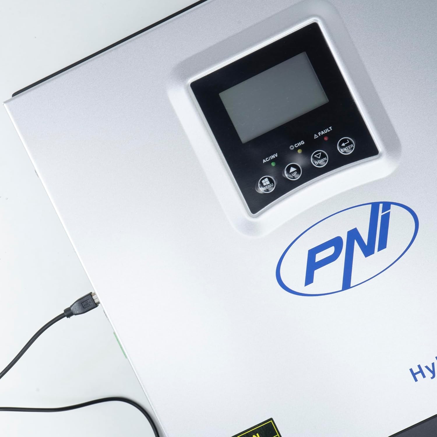
Figure 3.3: Close-up of the USB connection port on the inverter, used for PC monitoring.
3.2 PNI Smart Dongle-WLAN (Optional)

Figure 3.4: The PNI Smart Dongle-WLAN, an optional accessory for remote WiFi monitoring of the inverter.

Figure 3.5: The PNI Smart Dongle-WLAN connected to the inverter's dedicated port for WiFi communication.
4. Installation and Setup
4.1 Wall Mounting
The inverter is designed for wall mounting. Choose a location that is dry, well-ventilated, and protected from direct sunlight and moisture. Ensure sufficient clearance around the unit for proper airflow and heat dissipation. Use appropriate mounting hardware for your wall type.
4.2 System Connection Diagram

Figure 4.1: Basic application diagram showing the connections between solar panels, utility grid, generator, inverter, battery, and home loads. Note: Generator, PV modules, WiFi module, and battery are not included with the inverter unless specified.
4.3 Wiring Connections
Follow the diagram above and the labels on the inverter for correct wiring. Ensure all connections are secure and properly insulated. It is highly recommended that a qualified electrician performs all wiring.
- Solar Panel Connection: Connect your solar panels to the designated PV input terminals. Observe correct polarity (positive to positive, negative to negative). The maximum DC input voltage is 120 VDC.
- Battery Connection: Connect the 24V battery bank to the battery terminals. Ensure correct polarity. The inverter supports AGM, lead-acid, gel, and flooded lithium-ion batteries.
- AC Input (Grid/Generator): Connect the AC utility grid or a generator to the AC input terminals. This provides backup power and can charge batteries.
- AC Output (Loads): Connect your household loads to the AC output terminals.
4.4 Initial Power-Up
After all connections are made and verified:
- Turn on the battery breaker.
- Turn on the solar panel breaker (if applicable).
- Turn on the AC input breaker (if connected to grid/generator).
- Turn on the inverter's power switch.
- Observe the display for status indicators and initial readings.
5. Operating Modes
The PNI GreenHouse SC1800C PRO offers intelligent energy management with several configurable operating modes:
- Solar Priority Mode (SBU): In this mode, the inverter prioritizes power consumption from solar energy. If solar power is insufficient, it will draw from batteries. The utility grid acts as a backup.
- Battery Priority Mode: The inverter prioritizes drawing power from the batteries. Solar energy will charge the batteries. The utility grid is used only when battery voltage drops below a set threshold.
- Utility Priority Mode (UPS): This mode prioritizes power from the utility grid. Solar energy will charge the batteries. The inverter switches to battery power only when the grid is unavailable, functioning as an Uninterruptible Power Supply (UPS).
These modes can be configured via the inverter's multifunction display and dedicated menu for advanced settings.
5.1 Monitoring
The inverter supports monitoring through:
- PC Software (USB): Connect the inverter to a PC using the provided USB cable and dedicated software for detailed monitoring and analysis of parameters.
- Remote Monitoring (WiFi - Optional): With the optional PNI Smart Dongle-WLAN, you can monitor the inverter remotely via a mobile application or web interface.
6. Maintenance
Regular maintenance ensures optimal performance and longevity of your inverter. Always disconnect all power sources before performing any maintenance.
- Cleaning: Periodically clean the exterior of the inverter with a dry cloth. Ensure ventilation openings are free from dust and debris. Do not use liquid cleaners.
- Connection Checks: Annually inspect all wiring connections (solar, battery, AC input/output) for tightness and signs of corrosion. Tighten any loose connections.
- Battery Inspection: If using lead-acid batteries, check electrolyte levels and terminal condition as per battery manufacturer guidelines.
- Environmental Check: Ensure the installation environment remains within specified temperature and humidity ranges.
7. Troubleshooting
This section provides guidance for common issues. For complex problems, contact qualified service personnel.
| Problem/Alarm | Possible Cause | Solution |
|---|---|---|
| Low Battery Alarm | Battery voltage is below the low-voltage warning threshold. | Check battery charge level. Ensure solar panels are producing power or AC input is connected for charging. Reduce load. |
| Battery Disconnected Alarm | Battery cables are loose or disconnected. | Safely disconnect all power sources and check battery connections. Reconnect securely. |
| Overvoltage Alarm | Input voltage (PV or AC) exceeds safe limits. | Verify solar panel array voltage or AC input voltage. Ensure it is within the inverter's specifications. |
| AC Overload Protection | Connected loads exceed the inverter's output capacity. | Reduce the total load connected to the inverter. Check individual appliance power consumption. |
| No Output Power | Inverter off, low battery, overload, or fault. | Check if the inverter is powered on. Verify battery voltage. Check for overload or fault codes on the display. |
8. Specifications
| Feature | Specification |
|---|---|
| Brand | PNI |
| Model Number | PNI-SC1800P-DG |
| Rated Power | 3000 W |
| Peak Power | 6000 VA (0.5 seconds) |
| Battery Voltage | 24 V |
| Max. PV Input Power | 2000 W |
| Max. PV Input Voltage (Vmp) | 30 - 120 VDC |
| MPPT Solar Charge Current | 60 A (output to batteries) |
| AC Input Voltage | 230 V |
| AC Output Voltage | 230 V |
| Output Waveform | Pure Sine Wave |
| Output Frequency | 50/60 Hz |
| Max. AC Charge Current | 30 A |
| Inverter Efficiency | 90% ~ 93% |
| Operating Temperature | -26 °C to 80 °C |
| Dimensions (L x W x H) | 29 x 12 x 35 cm |
| Weight | 6.9 kg |
| Standby Consumption | ≈ 25 W (Energy saving mode ≈ 12.5 W) |
| Communication | USB, Optional WiFi Dongle |
9. Warranty and Support
For warranty information and technical support, please refer to the documentation provided with your purchase or contact your retailer. Keep your proof of purchase for warranty claims.


