
1. Introduction
The DALY Smart BMS (Battery Management System) is designed to provide comprehensive protection and intelligent management for LifePO4 lithium battery packs. This 8S 24V 40A model ensures enhanced battery safety by guarding against overcharging, over-discharging, overcurrent, short circuits, and extreme temperatures. It features a 2-in-1 Bluetooth/Wi-Fi dongle for convenient monitoring and parameter adjustment via mobile app or PC software, offering remote control capabilities. The built-in parallel circuit supports parallel use of battery packs and 485/CAN Bus communication, making it compatible with mainstream inverters.

The DALY Smart BMS is engineered for reliability and ease of use, providing essential features for optimal battery performance and longevity. Its robust design incorporates advanced thermal management and low power consumption, ensuring stable operation across various applications.

2. Setup and Installation
Proper installation is crucial for the safe and efficient operation of your DALY Smart BMS. Please follow these steps carefully. Refer to the wiring diagram for visual guidance.
2.1. Packing List Verification
Before beginning installation, ensure all components are present in the package:

| Item | Quantity |
|---|---|
| Smart BMS (8S 24V 40A) | 1 |
| B-P-Output Line | 1 |
| 2-in-1 BT/Wi-Fi Dongle | 1 |
| Sampling Cable | 1 |
| NTC (Thermistor) | 1 |
| CAN/485 5-pin Cable | 1 |
| Manual | 1 |
2.2. Wiring Instructions
Follow these steps for correct wiring. The diagram below illustrates the connections for a K series 60A BMS, but the principles apply to your 8S 24V 40A model.

- Step 1: Solder the sampling cables. The first cable in black from the sampling cable set connects to the negative terminal of the battery (B-). Subsequent red cables connect to the positive terminal of the first string of batteries, then the second string, and so on, until all cell positive terminals are connected.
- Step 2: Check the cables. After connecting the cables, measure the voltage between two adjacent cells starting from the header to ensure there are no wrong connections or missing connections.
- Step 3: Connect the output wires. Connect the B- wire of the BMS to the total negative terminal of the battery pack. Then, plug the sampling cable into the BMS. After activating the BMS, ensure that the voltage (battery voltage) between B+ & B- and the voltage between P+ & P- are consistent.
Note: The BMS will not activate until a charge is applied to the battery pack through the BMS. Without applying a charge, the BMS will not come online and will not be detectable by the app.
3. Operating Instructions
The DALY Smart BMS offers intelligent monitoring and control through its dedicated mobile application and PC software.
3.1. App Connection and Monitoring
The 2-in-1 Bluetooth/Wi-Fi dongle allows for flexible connectivity:
- Bluetooth: Easily connect with the app for local monitoring.
- Wi-Fi: Switch to Wi-Fi for long-distance control when Bluetooth is out of range. This requires connection to a Wi-Fi router.
Remotely monitor battery status and adjust parameters via the mobile app or PC software, whether you are at home, traveling, or operating a trolling motor.
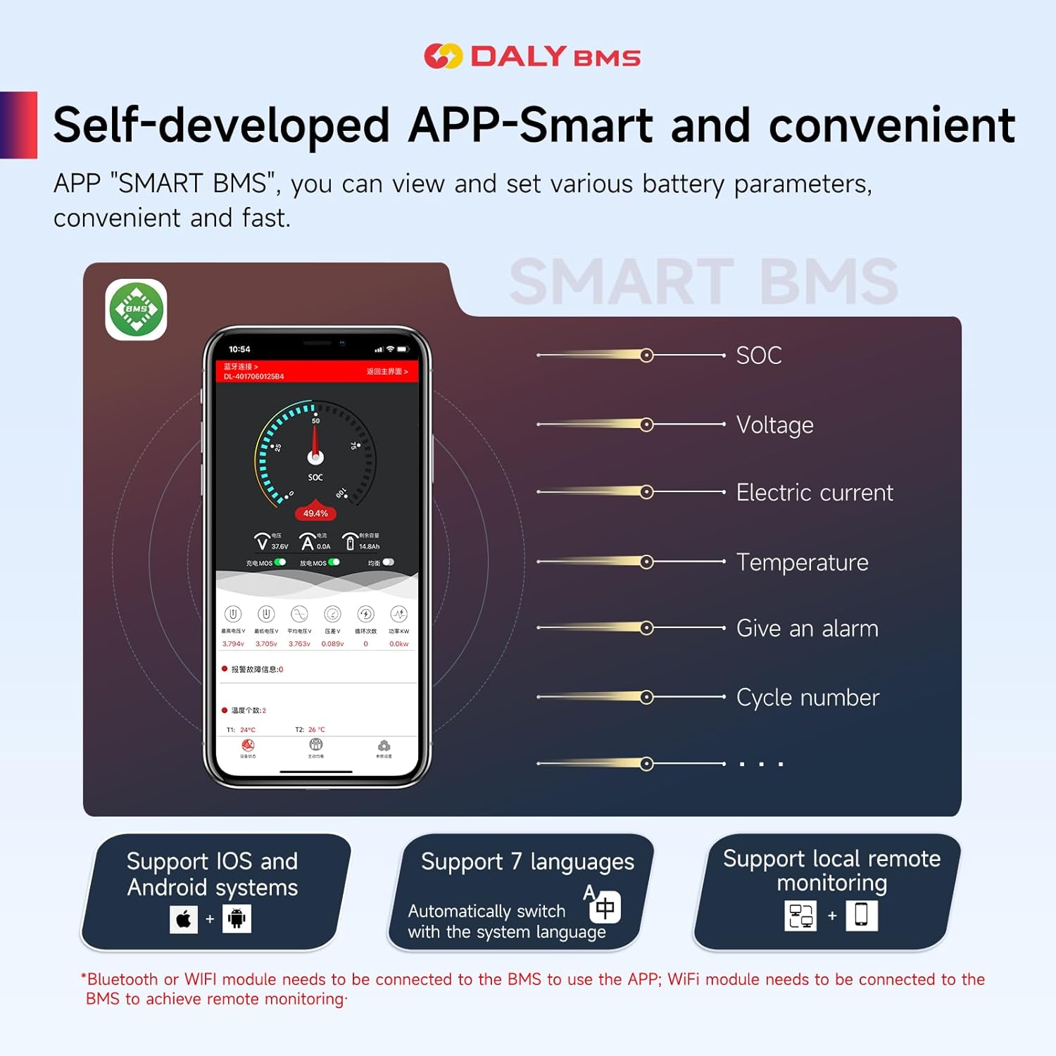
The app supports both iOS and Android systems and can automatically switch with the system language. It also supports local and remote monitoring.
3.2. Parallel Operation
The built-in parallel circuit of the DALY BMS supports the parallel use of battery packs and 485/CAN Bus parallel communication. This feature makes it suitable for integration with mainstream inverters on the market, allowing for scalable power solutions.
This video demonstrates the versatility and advanced features of the DALY K series Smart BMS, including its ability to support parallel battery configurations for increased capacity and power output.
4. Maintenance
To ensure the longevity and optimal performance of your DALY Smart BMS and battery pack, consider the following maintenance guidelines:
- Regular Monitoring: Periodically check battery parameters via the mobile app to identify any anomalies early.
- Connection Integrity: Ensure all wiring connections remain secure and free from corrosion. Loose connections can lead to performance issues or safety hazards.
- Environmental Conditions: Operate the BMS within its specified temperature range. Avoid exposing the unit to extreme heat, cold, or excessive moisture.
- Firmware Updates: Check for and install any available firmware updates for the BMS or mobile application to ensure you have the latest features and bug fixes.
- Cleaning: Keep the BMS unit clean and free from dust and debris. Use a dry, soft cloth for cleaning. Do not use liquid cleaners.
5. Troubleshooting
This section provides solutions to common issues you might encounter with your DALY Smart BMS.
5.1. Common Issues and Solutions
- BMS Not Activating/App Not Detecting:
Cause: The BMS requires an initial charge to be applied to the battery pack through the BMS to activate. It will not come online or be detected by the app until this occurs.
Solution: Connect a charger to the battery pack via the BMS and initiate charging. Once charging begins, the BMS should activate and become detectable.
- Incorrect Voltage Readings:
Cause: Loose or improperly connected sampling cables. Damaged sampling cable or BMS internal fault.
Solution: Double-check all sampling cable connections to ensure they are secure and in the correct order. Verify the voltage between adjacent cells. If the issue persists, contact customer support.
- Over-Protection Triggering Frequently:
Cause: Battery cells are unbalanced, or protection thresholds are set too aggressively. Could also indicate a faulty cell or an issue with the load/charger.
Solution: Use the app to check individual cell voltages and initiate balancing if necessary. Review and adjust protection parameters in the app if they are too sensitive for your application. Inspect battery cells for damage.
- Bluetooth/Wi-Fi Connectivity Issues:
Cause: Dongle not properly connected, out of range, or interference.
Solution: Ensure the 2-in-1 dongle is securely plugged into the BMS. Move closer to the BMS for Bluetooth connection. For Wi-Fi, ensure the dongle is within range of a stable Wi-Fi network and correctly configured.
6. Specifications
Detailed technical specifications for the DALY Smart BMS 8S 24V 40A model.
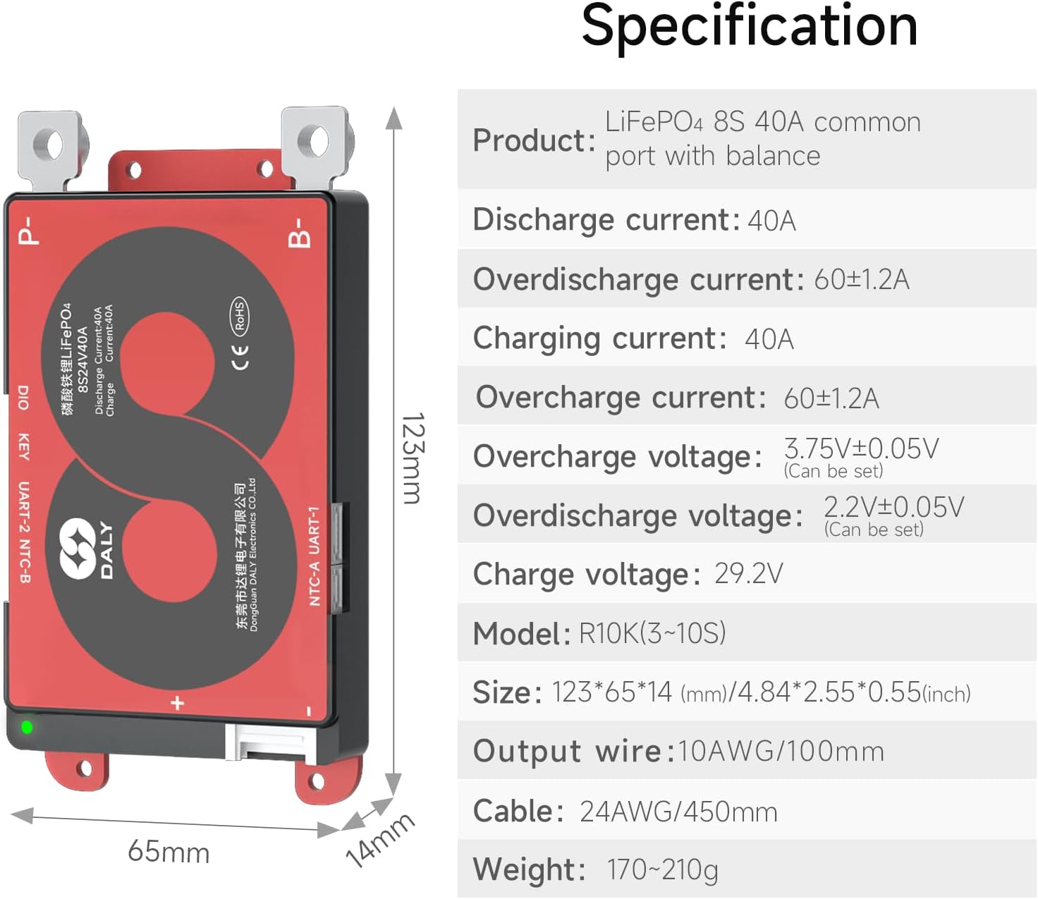
| Parameter | Value |
|---|---|
| Product Type | LifePO4 8S 40A common port with balance |
| Discharge Current | 40A |
| Overdischarge Current | 60±1.2A |
| Charging Current | 40A |
| Overcharge Current | 60±1.2A |
| Overcharge Voltage | 3.75V±0.05V (Can be set) |
| Overdischarge Voltage | 2.2V±0.05V (Can be set) |
| Charge Voltage | 29.2V |
| Model | R10K(3-10S) |
| Size (L×W×H) | 123*65*14 mm / 4.84*2.55*0.55 inches |
| Output Wire | 10AWG/100mm |
| Cable | 24AWG/450mm |
| Weight | 170~210g |
| Product Dimensions | 4.84 x 2.56 x 0.55 inches |
| Item Weight | 7.4 ounces |
| Input Voltage | 24 Volts (DC) |
| Output Voltage | 24 Volts (DC) |
7. Warranty and Support
DALY provides a warranty for its Smart BMS products to ensure customer satisfaction and product reliability.
7.1. Warranty Information
This DALY Smart BMS comes with a 3 Years Warranty. This warranty covers defects in materials and workmanship under normal use. Please retain your proof of purchase for warranty claims.
7.2. Certifications
The DALY Smart BMS is ISO/FCC/RoHS/PSE/CE APPROVED, ensuring compliance with international quality and safety standards.
7.3. Customer Support
For technical assistance, troubleshooting, or warranty claims, please contact DALY customer support. You can find contact information on the official DALY website or through your purchase platform.
Visit the DALY Store on Amazon for more information and support resources.


