Introduction
The AURSINC NanoVNA-F V2 is a versatile vector network analyzer designed for both hobbyists and professionals. It features a rugged and durable aluminum alloy casing that shields electromagnetic interference, ensuring precise measurements. With an expanded frequency range of 50KHz to 3GHz, it supports measurements of S-parameters, voltage standing wave ratio (SWR), phase map, group delay, Smith chart, DELAY, POLAR, LINEAR, and more.
Equipped with a 4.3-inch IPS TFT LCD screen and a 5000mAh battery, it offers extended usage time and a clear viewing experience. The device also includes a built-in 5V output for charging Android phones or tablets, enhancing its utility in the field. The included RF Demo Kit provides a comprehensive test board for learning and calibrating the NanoVNA, making it an ideal tool for various radio design and simulation applications.
What's in the Box
Your AURSINC NanoVNA-F V2 package includes the following components:
- 1x NanoVNA-F V2 Host (with latest Firmware 0.4.0, 4.3-inch IPS TFT LCD screen, 5000mAh battery)
- 1x SMA Open Calibration Kit
- 1x SMA Short-circuit Calibration Kit
- 1x SMA 50Ω Load Calibration Kit
- 1x SMA-KK Double-Head Female Hole Adapter
- 1x SMA-JJ Double-Head Male Pin Adapter
- 1x SMA-JKW Elbow Outer Screw Inner Hole To Inner Screw Inner Needles Adapter
- 2x 20cm SMA-JJ RG405 RF Cable
- 1x USB Type-C Data Cable
- 1x Stylus
- 1x PCB RF Tester Board (RF Demo Kit)
- 2x 20cm Adapter Cables (for RF Demo Kit)

Image: All components included in the NanoVNA-F V2 package.
Product Features and Components
Device Overview
The NanoVNA-F V2 features a robust design with key components for optimal performance:
- 4.3-inch IPS TFT LCD Screen: Provides a clear and wide viewing angle for measurements.
- Frequency Range: Capable of measurements from 50KHz to 3GHz.
- Ports: Equipped with PORT 1 (S11) and PORT 2 (S21) for comprehensive S-parameter measurements.
- Connectivity: Includes a USB Type-C port for charging and PC connection, and a USB-A port for 5V/1A output.
- Navigation Buttons: Located on the side for easy menu navigation and control.
- Status LED: Indicates the device's operational status.

Image: The 4.3-inch screen and frequency range of the NanoVNA-F V2.

Image: Side view of the NanoVNA-F V2 highlighting its ports and controls.
RF Demo Kit
The included RF Demo Kit is a PCB RF tester board designed for learning and testing various RF circuits. It features 18 functional modules for measuring different filter types and impedance characteristics.
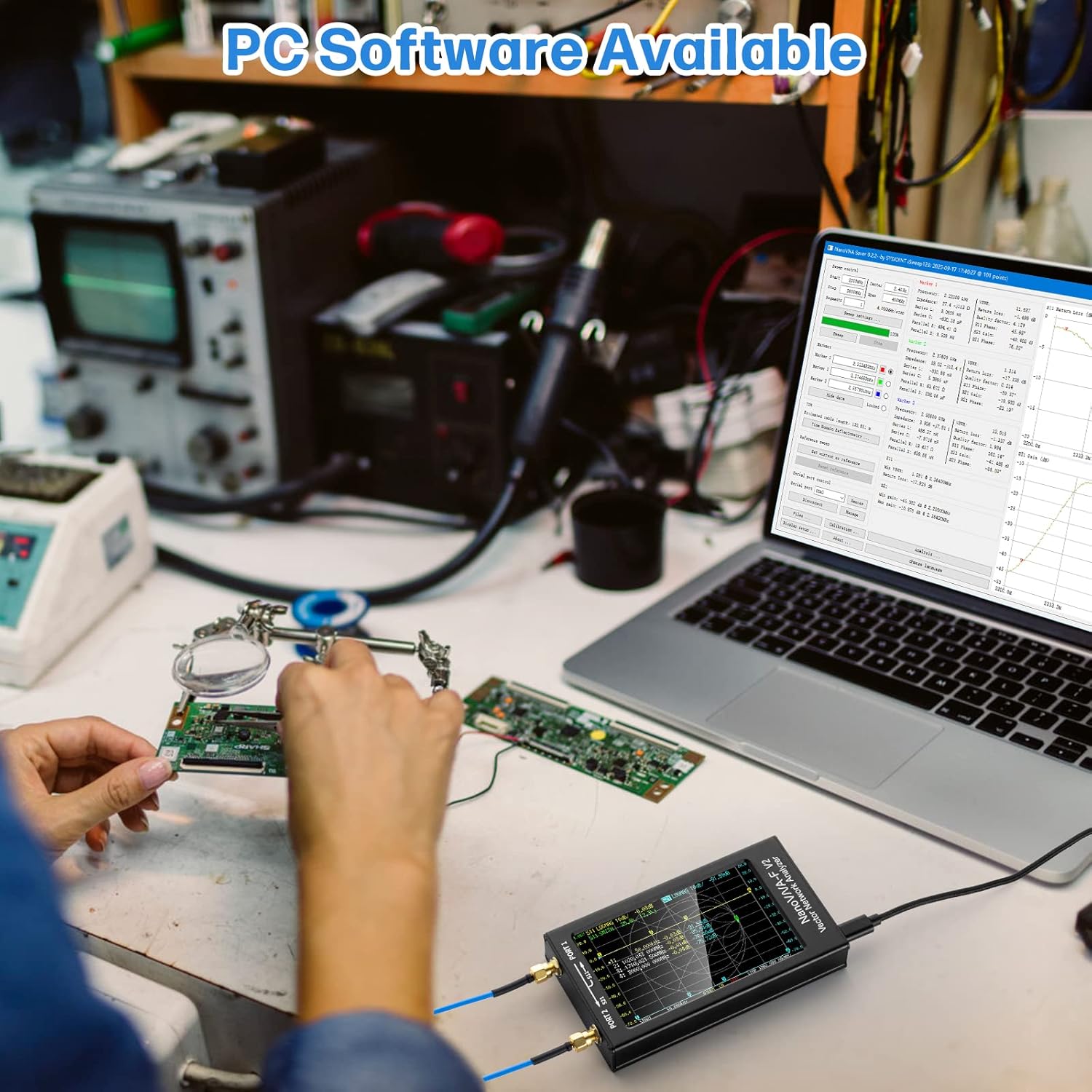
Image: The RF Demo Kit PCB board.

Image: Dimensions of the RF Demo Kit board.

Image: The RF Demo Kit in use with the NanoVNA-F V2.

Image: Example of a Smith Chart display for Circuit 1 on the RF Demo Kit.
Setup and Calibration
Before taking accurate measurements, it is crucial to properly set up and calibrate your NanoVNA-F V2. This process ensures the device provides reliable data across its frequency range.
Connecting to PC/Android
The NanoVNA-F V2 can be controlled via PC software (NanoVNA Saver) or an Android mobile phone. This allows for data extraction, display, and saving in Touchstone files for further analysis and simulation.

Image: NanoVNA-F V2 connected to a PC for software control.
Calibration Steps
The RF Demo Kit includes specific circuits for calibration. Follow these steps for accurate calibration:
- Connect the two 20CM SMA to IPEX adapter cables to the NanoVNA-F V2 machine.
- Recalibrate the machine using the 13 Short, 14 Open, 15 Load, and 16 Thru circuits on the test board.
- Save the calibrated parameters to SAVE 0 on the device.
For detailed calibration procedures, refer to the official documentation available on the SYSJOINT website.
Operating Instructions
The NanoVNA-F V2 allows for various measurements essential for RF analysis. After successful calibration, you can proceed with testing different components and antennas.
Antenna Measurement Capabilities
The device supports a wide range of antenna measurements, including SWR, MF, HF, VHF, UHF, SSB, Balun, Short Wave, and Smith chart analysis.

Image: Various antenna types measurable with the NanoVNA-F V2.
Interpreting Measurements
The NanoVNA-F V2 displays measurement results graphically on its screen. You can analyze SWR curves to identify optimal operating frequencies for antennas. The Smith chart provides detailed impedance information, including resistive and reactive components, which is crucial for antenna tuning and matching.
Use the stylus to navigate the on-screen menus and adjust settings such as start/stop frequencies, display formats (SWR, Smith Chart, LogMag, Phase, Delay), and active traces. The device allows for up to four traces to be displayed simultaneously, each configurable to show different parameters.
Maintenance
To ensure the longevity and optimal performance of your AURSINC NanoVNA-F V2, follow these maintenance guidelines:
- Cleaning: Use a soft, dry cloth to clean the device. Avoid abrasive cleaners or solvents that could damage the screen or casing.
- Port Protection: Always keep the dust caps on the SMA ports when not in use. This prevents dust and debris from entering and protects against stray static discharge.
- Storage: Store the NanoVNA in its original carrying case in a cool, dry place away from direct sunlight and extreme temperatures.
- Battery Care: For long-term storage, ensure the battery is charged to approximately 50-70% to maintain battery health. Avoid fully discharging the battery for extended periods.
- Firmware Updates: Periodically check the official SYSJOINT website for firmware updates to ensure your device has the latest features and performance improvements.
Troubleshooting
If you encounter issues with your NanoVNA-F V2, try the following troubleshooting steps:
- Device Not Powering On:
- Ensure the battery is charged. Connect the device to a power source using the USB Type-C cable.
- Check the on/off switch on the side of the device.
- Inaccurate Measurements:
- Perform a full calibration (Open, Short, Load, Thru) before taking measurements.
- Ensure all cables and adapters are securely connected and are not damaged.
- Verify that the correct frequency range is set for your measurement.
- Screen Unresponsive:
- Use the provided stylus for precise touch input.
- Restart the device by turning it off and on.
- PC Software Connectivity Issues:
- Ensure the correct drivers are installed on your PC.
- Verify the USB Type-C cable is functioning correctly and securely connected.
- Check the official SYSJOINT website for software updates or troubleshooting guides.
For further assistance, please contact AURSINC customer support.
Specifications
| Parameter | Specification | Conditions |
|---|---|---|
| Frequency Range | 50KHz-3GHz | |
| S21 Dynamic Range | 70dB | 50KHz-1.5GHz |
| S21 Dynamic Range | 60dB | 1.5GHz-3GHz |
| S11 Dynamic Range | 50dB | 50KHz-1.5GHz |
| S11 Dynamic Range | 40dB | 1.5GHz-3GHz |
| Screen Size | 4.3-inch IPS TFT LCD | 800*480 resolution, resistive touch |
| Battery Capacity | 5000mAh Lithium Battery | Up to 7 hours usage |
| USB Output | 5V/1A | For charging external devices |
| Max Sweep Points | 201 |
Warranty and Support
AURSINC is dedicated to providing professional measurement tools and electronic products. We are always ready to assist you with any questions or concerns.
- Return Policy: 30 days for refund/replacement.
- Warranty: 365 days.
- Customer Service: Available within 24 hours for assistance.
Thank you for considering AURSINC as your trusted partner for all your measurement tool needs.


