
1. Introduction
The GeRRiT Generator Speed Controller XS-400B-03 is an advanced electronic device designed for precise control of engine speed in generator applications. Utilizing a closed-loop control system, it ensures rapid and accurate response to instantaneous load changes, maintaining stable engine operation. This controller is engineered for high reliability, capable of operating effectively within environments subject to electromagnetic interference. It features full closed-loop control technology for fast and accurate engine speed regulation and is designed for easy installation and pre-adjustments, suitable for various machine types.
2. Product Overview
The XS-400B-03 speed controller is housed in a durable, compact enclosure, designed for industrial environments. It features clearly labeled terminal blocks for electrical connections and adjustable potentiometers for fine-tuning performance parameters.

Figure 2.1: Top View of the XS-400B-03 Speed Controller. This image displays the main control panel, including the terminal blocks labeled S+, S-, 1-5 (Actuator), 6-12 (Magnetic Pickup, Source DC, OP), and adjustment potentiometers for DR (Droop), GAIN, SOURCE, ACTUATOR, and SP (Speed).
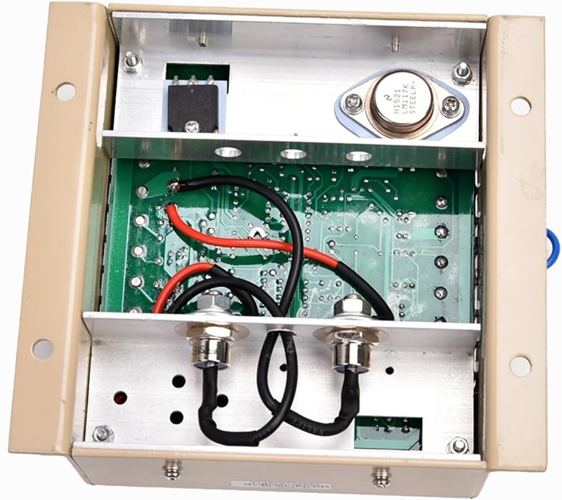
Figure 2.2: Internal View of the XS-400B-03 Speed Controller. This image reveals the internal circuit board, demonstrating the robust electronic design and component layout for reliable operation.
3. Setup and Installation
3.1 Mounting
Mount the XS-400B-03 controller securely in a location protected from excessive vibration, moisture, and extreme temperatures. Ensure adequate ventilation around the unit to prevent overheating. Use the mounting holes provided on the enclosure for stable installation.
3.2 Wiring Connections
Refer to Figure 2.1 for the terminal block layout. Ensure all connections are secure and correctly polarized where applicable. Use appropriate gauge wiring for all connections.
- S+, S- (Power Input): Connect to the DC power supply for the controller. Observe correct polarity.
- Terminals 1-5 (Actuator): These terminals connect to the engine's actuator, which controls the fuel supply. Consult your engine's manual for specific actuator wiring.
- Terminals 6-7 (Magnetic Pickup): Connect these to the magnetic speed pickup sensor on the engine. This sensor provides engine speed feedback to the controller.
- Terminals 8-9 (Source DC): Additional DC power input or output, depending on system configuration.
- Terminals 10-12 (OP - Output): These are typically output terminals for various control signals or auxiliary functions.
3.3 Initial Adjustments
The controller features several potentiometers for initial setup and fine-tuning:
- DR (Droop): Adjusts the droop characteristic, which allows for a slight decrease in engine speed as load increases. This can improve stability in some systems.
- GAIN: Controls the sensitivity of the controller to speed deviations. Higher gain results in faster response but can lead to instability if set too high.
- SOURCE: Typically adjusts the input signal sensitivity or source voltage.
- ACTUATOR: Adjusts the output signal to the actuator.
- SP (Speed): Sets the desired engine operating speed.
Start with factory default or recommended settings if available, then make small, incremental adjustments while monitoring engine performance.
4. Operating Principles
The XS-400B-03 operates on a full closed-loop control principle. It continuously monitors the engine's rotational speed via a magnetic pickup sensor. This real-time speed feedback is compared against a user-defined setpoint (adjusted by the SP potentiometer). Any deviation between the actual and desired speed triggers the controller to adjust its output signal to the engine's actuator. The actuator then modifies the fuel supply, bringing the engine speed back to the setpoint. This rapid and precise response ensures stable generator output under varying load conditions, making it suitable for a wide range of engines.
5. Maintenance
The GeRRiT XS-400B-03 speed controller is designed for long-term reliability with minimal maintenance. However, periodic checks are recommended:
- Visual Inspection: Regularly inspect the controller for any signs of physical damage, such as cracks, loose components, or discoloration.
- Connection Integrity: Ensure all wiring connections to the terminal blocks are tight and free from corrosion. Loose connections can lead to intermittent operation or failure.
- Cleanliness: Keep the unit clean and free from dust, dirt, and moisture. Use a soft, dry cloth for cleaning. Do not use solvents or abrasive cleaners.
- Environment: Verify that the operating environment remains within the specified temperature and humidity ranges.
There are no user-serviceable parts inside the controller. Any internal issues should be addressed by qualified service personnel.
6. Troubleshooting
This section provides guidance for common issues. For complex problems, consult qualified technical personnel.
| Symptom | Possible Cause | Solution |
|---|---|---|
| Engine speed unstable or hunting | Incorrect GAIN or DR (Droop) adjustment. Loose magnetic pickup connection. | Adjust GAIN and DR potentiometers incrementally. Ensure magnetic pickup wiring is secure. |
| Engine fails to reach or maintain desired speed | Incorrect SP (Speed) setting. Faulty magnetic pickup sensor. Actuator malfunction. Insufficient power supply. | Adjust SP potentiometer. Check magnetic pickup sensor and its wiring. Verify actuator operation. Ensure stable DC power to the controller. |
| No response from controller / Engine does not react to adjustments | No power to the controller. Incorrect wiring. Internal fault. | Check power input (S+, S-). Verify all wiring connections. If power is present and wiring is correct, contact technical support. |
| Over-speed or Under-speed condition | Improper GAIN/DR settings. Magnetic pickup signal issues. | Re-adjust GAIN and DR. Inspect magnetic pickup for damage or incorrect gap. |
7. Specifications
The following are the technical specifications for the GeRRiT Generator Speed Controller XS-400B-03:
| Feature | Specification |
|---|---|
| Brand | GERRIT |
| Model Number | XS-400B-03 |
| Package Dimensions | 1.18 x 0.79 x 0.39 inches |
| Item Weight | 7.1 ounces (200 Grams) |
| Material | Copper (Internal components) |
| Assembly Required | No (Unit is pre-assembled) |
| Number of Pieces | 1 |
| ASIN | B0CXDBC6SF |
8. Warranty and Support
For warranty information, technical assistance, or service inquiries regarding your GeRRiT Generator Speed Controller XS-400B-03, please contact your authorized GeRRiT dealer or the point of purchase. It is recommended to retain your purchase receipt as proof of purchase for any warranty claims. For the most up-to-date support resources, please refer to the official GeRRiT website.