
1. Introduction
This manual provides detailed instructions for the installation, operation, and maintenance of the Cryfokt K329E Sliding Gate Operator Control Board. This universal PCB circuit is designed for automatic sliding gate motors, offering features such as adjustable slow speed settings, customizable motor force, and LED indicators for easy troubleshooting. Please read this manual thoroughly before installation and use to ensure proper function and safety.
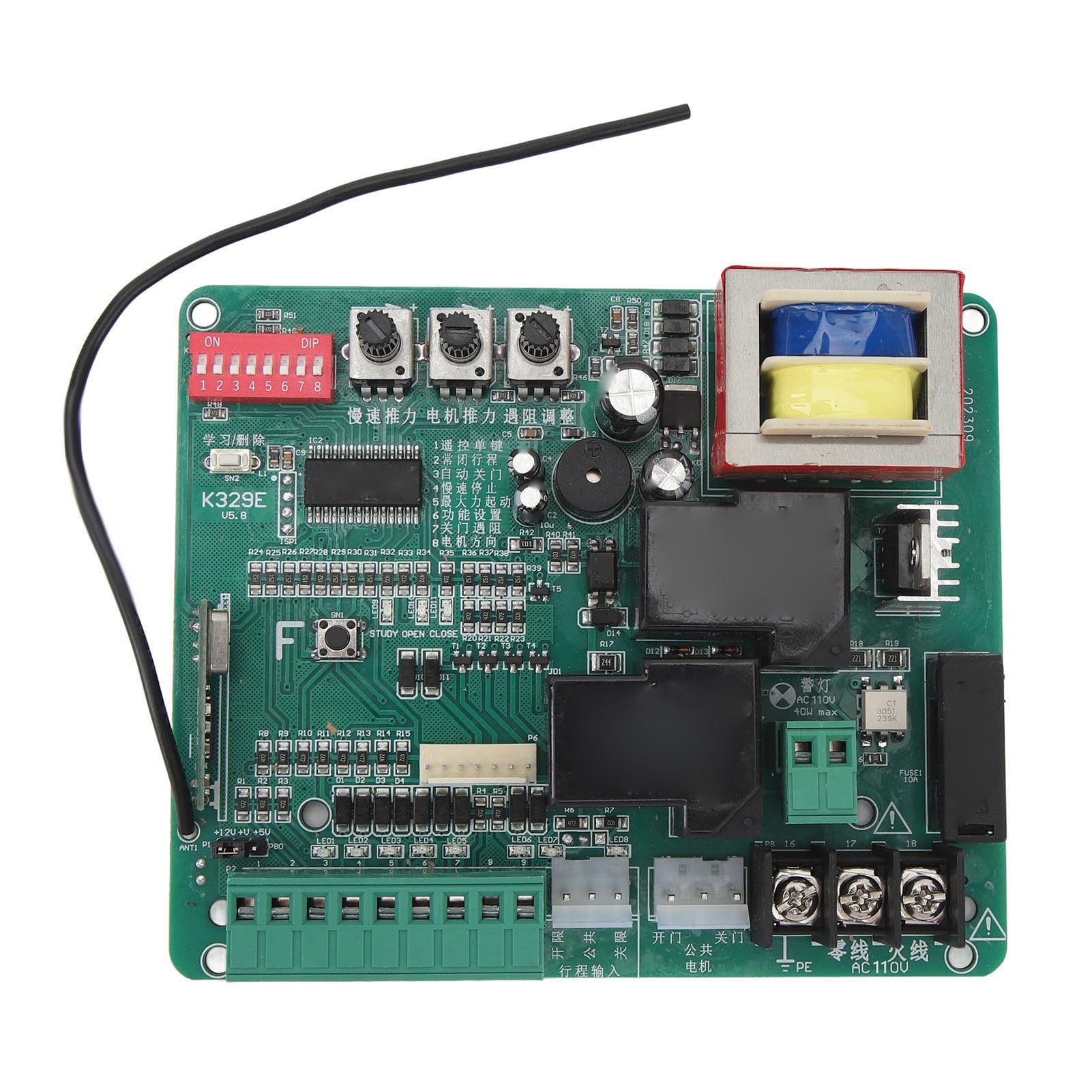
Image 1.1: Overview of the Cryfokt K329E Sliding Gate Operator Control Board. The green circuit board features various electronic components, including relays, capacitors, a transformer, and terminal blocks for connections.
2. Safety Information
WARNING: Improper installation or use can lead to serious injury or damage. Always follow these safety guidelines:
- Ensure all power is disconnected before performing any installation, maintenance, or repair work.
- Installation should only be performed by qualified personnel familiar with electrical systems and gate operators.
- Verify that the power supply voltage matches the requirements of the control board (AC 110V or AC 220V, depending on the model).
- Keep hands and loose clothing clear of moving gate parts during operation.
- Do not allow children to play with or operate the gate controls.
- Regularly inspect the gate and its components for signs of wear or damage.
- Ensure all safety devices, such as photocells or safety edges, are correctly installed and functioning.
3. Product Features
The Cryfokt K329E Control Board offers the following key features:
- Adjustable Slow Speed Function: Ensures smooth and stable operation of the gate with customizable slow speed settings during opening and closing.
- Customizable Motor Force Settings: Allows adjustment of motor power to prevent injuries or damage to the gate or obstacles.
- Automatic Stop Feature: The motor automatically stops when encountering obstacles, enhancing safety.
- Convenient One-Button Control: Enables easy manual opening and closing of the gate with strong anti-interference capabilities.
- LED Indicators: Provides visual feedback for each step of action, facilitating maintenance and troubleshooting.
4. Package Contents
The package includes:
- 1 x Cryfokt K329E Sliding Gate Circuit Board
5. Setup and Installation
Proper installation is crucial for the safe and efficient operation of your sliding gate. Refer to the wiring diagram and component overview below for guidance.

Image 5.1: Detailed view of the terminal blocks and DIP switches on the Cryfokt K329E Control Board. Key connections for power, motor, and control signals are visible.
5.1. Wiring Connections
Connect the control board to your gate motor and power supply according to the following general guidelines. Always consult the specific wiring diagram provided with your gate motor for precise connections.
- Power Supply (AC 110V/220V): Connect the main AC power to the designated "AC" terminals on the board. Ensure correct voltage matching.
- Motor Connections: Connect the gate motor's open, close, and common wires to the "MOTOR" terminals (L1, L2, COM). A capacitor may be required for certain motor types; refer to your motor's manual.
- Limit Switches: Connect the limit switches (Open, Close, Common) to the "LIMIT" terminals (O.P, C.L, COM). These switches define the gate's fully open and fully closed positions.
- Control Inputs: Connect external control devices such as push buttons, keypads, or remote receivers to the "KEY" terminals (OP, CL, STP, COM).
- Safety Devices: Connect safety photocells or other safety sensors to the appropriate input terminals, typically labeled "FSL" or similar, ensuring they are wired to interrupt gate movement if an obstruction is detected.
- Grounding: Ensure the board and gate motor are properly grounded to prevent electrical hazards.
Video 5.2: This video demonstrates the Cryfokt K329E Sliding Gate Operator Control Board, showcasing its various components and potential connection points. It provides a visual overview of the board's layout and features.
5.2. DIP Switch Settings
The control board features DIP switches (typically labeled 1-8) to configure various operational parameters. Refer to the markings on the board or a separate diagram for specific functions of each switch. Common settings include:
- Automatic closing time delay.
- Soft start/stop function.
- Photocell function (normally open/normally closed).
- Motor direction.

Image 5.3: Close-up view of the red DIP switch block and three potentiometers on the Cryfokt K329E Control Board. These are used for fine-tuning operational parameters such as motor force and speed.
5.3. Potentiometer Adjustments
Three potentiometers are typically present on the board for adjusting motor force, slow speed, and other timing parameters. Use a small screwdriver to carefully turn these knobs to achieve desired performance.
- Motor Force: Adjusts the power delivered to the motor. Set it to the minimum required for smooth operation to prevent excessive strain or damage.
- Slow Speed: Controls the speed of the gate during its soft start and soft stop phases.
- Auto-Close Time: Sets the delay before the gate automatically closes after opening (if enabled via DIP switches).
6. Operating Instructions
Once the control board is correctly installed and configured, operating your sliding gate is straightforward.
- Manual Open/Close: Press the designated open or close button on your remote control or wired push button. The gate will move to its fully open or closed position.
- Stop Function: Press the stop button at any point to halt the gate's movement.
- Automatic Closing: If enabled, the gate will automatically close after a set delay once it reaches the fully open position.
- Obstacle Detection: If the gate encounters an obstacle during closing, it will automatically stop or reverse to prevent damage or injury. During opening, it will stop.
7. Maintenance
Regular maintenance ensures the longevity and reliable operation of your gate system.
- Visual Inspection: Periodically check the control board for any signs of damage, loose connections, or corrosion.
- Cleanliness: Keep the control board enclosure clean and free from dust, moisture, and insects.
- Gate Mechanism: Ensure the gate itself is well-maintained, with tracks clear and moving parts lubricated.
- Safety Devices: Test all safety devices (e.g., photocells) regularly to confirm they are functioning correctly.
- Power Disconnection: Always disconnect power before performing any cleaning or inspection of the control board.
8. Troubleshooting
The LED indicators on the control board can assist in diagnosing common issues.
| Problem | Possible Cause | Solution |
|---|---|---|
| Gate does not respond to commands. | No power, remote control battery low, wiring issue, safety device activated. | Check power supply. Replace remote battery. Inspect wiring connections. Check LED indicators for safety device status. |
| Gate stops unexpectedly. | Obstacle detected, limit switch fault, motor overload. | Clear any obstructions. Check limit switch connections. Reduce motor force if set too high. |
| Gate opens/closes partially. | Limit switches incorrectly set or faulty. | Adjust or inspect limit switches. |
| LED indicators are off. | No power to the board. | Verify main power connection and fuse. |
If problems persist after attempting these solutions, contact qualified technical support.
9. Specifications
| Item Type | Sliding Gate Circuit Board |
| Material | Electronic components |
| Scope of Application | Motor controller for automatic sliding gates |
| Product Size | 130 x 108 mm (5.12 x 4.25 inches) |
| Weight | 311 g (10.97 oz) |
| Mounting Hole Distance | 122x85x115 mm (4.8x3.3x4.5 inches), 100 mm (3.9 inches) |
| Model Number | Cryfoktpfb0idntga-12 |
| Manufacturer | Cryfokt |
10. Warranty and Support
Information regarding product warranty and customer support is not available in the provided product data. Please refer to the product packaging or contact the retailer/manufacturer directly for details on warranty coverage and technical assistance.