1. Introduction
This manual provides essential instructions for the installation, operation, and maintenance of your STEPPERONLINE Closed Loop Stepper Motor 1 Axis CNC Kit. This kit is designed for precision motion control applications, offering enhanced accuracy and reliability compared to open-loop systems. Please read this manual thoroughly before using the product to ensure correct setup and optimal performance.
2. Product Overview
The STEPPERONLINE Closed Loop Stepper Motor 1 Axis CNC Kit combines a high-torque Nema 17 stepper motor with an integrated encoder and a compatible closed-loop stepper driver. This system provides real-time position feedback, preventing step loss and ensuring precise positioning for various applications such as 3D printers, CNC machines, carving machines, dispensers, and other automation equipment.
2.1 Kit Components
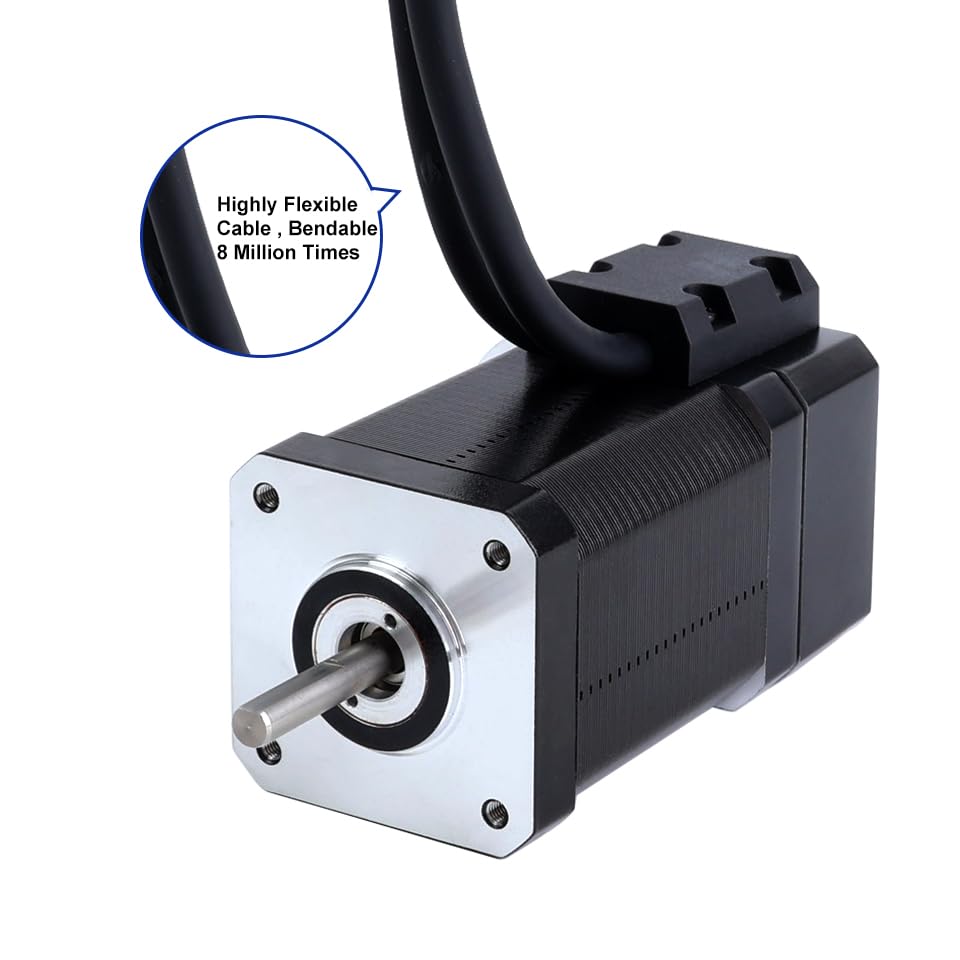
- 1 x Nema 17 Closed Loop Stepper Motor (Model: 17HS24-2004D-E1K) with Encoder 1000PPR (4000CPR)
- 1 x Closed Loop Stepper Driver (Model: CL42T-V4.1) 0-3.0A, 24-48VDC
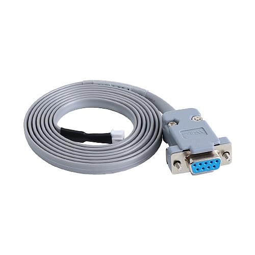
- 1 x RS232 Debugging Cable (Model: CABLE-PC-1)

3. Specifications
3.1 Motor Specifications (17HS24-2004D-E1K)
- Number of Phases: 2
- Step Angle: 1.8 degrees
- Holding Torque: 80 Ncm (113.29 oz.in)
- Rated Current/Phase: 2.0 A
- Phase Resistance: 1.3 ohms
- Inductance: 2.7 mH ± 20% (1KHz)
- Frame Size: 42 x 42 mm
- Body Length: 80 mm
- Shaft Diameter: Φ5 mm
- Shaft Length: 24 mm
- D-Cut Shaft Length: 15 mm
- Lead Length: 500 mm

3.2 Encoder Specifications
- Output Circuit Type: Differential type
- Encoder Type: Optical Incremental
- Encoder Resolution: 1000 PPR (4000 CPR)
- Output Signal Channels: 2 channels
- Supply Voltage: 5V (Min/Max)
- Output High Voltage: <4V
- Output Low Voltage: <1V
3.3 Driver Specifications (CL42T-V4.1)
- Output Peak Current: 0~3A
- Input Voltage: +24~48VDC (Typical 24VDC)
- Logic Signal Current: 7~16mA (Typical 10mA)
- Pulse Input Frequency: 0~200kHz
- Pulse Width: 2.5 µS
- Debugging Interface: RS232 available
- Features: Low noise and vibration, smooth motion
- Protections: Over voltage, over current, position following error

3.4 General Specifications
- Package Dimensions: 9.84 x 7.09 x 3.54 inches
- Weight: 2.4 Pounds
- Manufacturer: STEPPERONLINE
4. Setup and Installation
4.1 Power Supply Requirements
- The driver requires a DC power supply between 24VDC and 48VDC. A typical operating voltage is 24VDC.
- Ensure the power supply can provide sufficient current for the motor's peak current requirements (up to 3A).
- Connect the power supply to the +VDC and GND terminals on the driver. Observe polarity.
4.2 Wiring Connections
Carefully connect the motor, encoder, and control signals to the CL42T driver as described below. Refer to Figure 4 for terminal locations on the driver.
- Motor to Driver: Connect the motor phase wires (A+, A-, B+, B-) to the corresponding terminals on the driver. Ensure correct phase matching.
- Encoder to Driver: The motor's integrated encoder connects directly to the driver's encoder input port. This connection is crucial for closed-loop operation.
- Control Signals: Connect your controller's pulse (PUL+ / PUL-), direction (DIR+ / DIR-), and enable (ENA+ / ENA-) signals to the driver. Use differential connections for noise immunity.
- Alarm Output: The ALM/P and COM terminals provide an alarm output for error conditions.
- Brake Output: The BRK and COM terminals provide a brake output, if applicable to your system.
5. Operation
5.1 Driver Configuration (DIP Switches)
The CL42T driver features DIP switches (SW1-SW8) for configuring microstep resolution, output current, and control mode. Ensure the power is off before changing DIP switch settings.
5.1.1 Microstep Resolution Setting (SW1-SW4)
Set the desired microstep resolution using DIP switches SW1 to SW4 according to the table below. 'on' typically means the switch is down, 'off' means up.
| Pulse/rev | SW1 | SW2 | SW3 | SW4 |
|---|---|---|---|---|
| Default | on | on | on | on |
| 800 | off | on | on | on |
| 1600 | on | off | on | on |
| 3200 | off | off | on | on |
| 6400 | on | on | off | on |
| 12800 | off | on | off | on |
| 25600 | on | off | off | on |
| 51200 | off | off | off | on |
| 1000 | on | on | on | off |
| 2000 | off | on | on | off |
| 4000 | on | off | on | off |
| 8000 | off | off | on | off |
| 10000 | on | on | off | off |
| 20000 | off | on | off | off |
| 40000 | on | off | off | off |
| 80000 | off | off | off | off |
5.1.2 Output Current Setting (SW5-SW7)
Adjust the output peak current using DIP switches SW5 to SW7. Select a current setting appropriate for your motor to prevent overheating and ensure optimal performance.
| Peak Current | RMS Current | Code | SW5 | SW6 | SW7 |
|---|---|---|---|---|---|
| 0.8A | 0.6A | 0-3 | on | on | on |
| 1.4A | 1A | 4-7 | off | on | on |
| 2.1A | 1.5A | 8-B | on | off | on |
| 2.8A | 2A | C-F | off | off | on |
5.1.3 Control Mode Setting (SW8)
SW8 configures the control mode and pulse input type. For closed-loop operation, ensure SW8 is set to 'ON'.
| SW8 Setting | Control Mode | Direction Mode | Pulse Input Mode |
|---|---|---|---|
| ON | Closed Loop | CCW | Pulse/Direction |
| OFF | Open Loop | CW | CW/CCW |
5.2 Control Signals
- PUL (Pulse): Input signal for motor movement. Each pulse corresponds to a microstep.
- DIR (Direction): Input signal for motor rotation direction. High or low state determines direction.
- ENA (Enable): Input signal to enable or disable the driver. When disabled, the motor is free-spinning.
6. Maintenance
- Cleaning: Keep the driver and motor free from dust and debris. Use a soft, dry cloth for cleaning. Avoid liquid cleaners.
- Ventilation: Ensure adequate airflow around the driver to prevent overheating. Do not obstruct ventilation holes.
- Connections: Periodically check all wiring connections for tightness and integrity. Loose connections can lead to intermittent operation or damage.
- Environment: Operate the kit within its specified temperature and humidity ranges.
7. Troubleshooting
- Motor Not Moving:
- Check power supply voltage and current.
- Verify PUL, DIR, and ENA signal connections and levels from the controller.
- Ensure DIP switch settings for current and microsteps are correct.
- Check motor wiring for correct phase connections.
- Motor Overheating:
- Reduce the output current setting via DIP switches (SW5-SW7).
- Ensure adequate heat dissipation and ventilation.
- Verify the motor load is within its torque capabilities.
- Motor Vibrates/Makes Noise:
- Check for loose mechanical connections.
- Verify microstep settings. Higher microsteps generally lead to smoother operation.
- Ensure motor phase wiring is correct.
- Loss of Steps/Position Error:
- Confirm SW8 is set to 'ON' for closed-loop operation.
- Check encoder connections for integrity.
- Ensure the motor is not overloaded.
- Use the RS232 debugging interface to check for specific error codes if available.
8. Warranty and Support
STEPPERONLINE products are manufactured to high-quality standards. For specific warranty information, technical support, or service inquiries, please refer to the official STEPPERONLINE website or contact their customer service directly. Keep your purchase receipt for warranty claims.
You can visit the STEPPERONLINE store for more information: STEPPERONLINE Store