1. Introduction
This manual provides essential instructions for the installation, operation, and maintenance of your Walfront 100A MPPT Solar Charge Controller. This advanced controller utilizes Maximum Power Point Tracking (MPPT) technology to efficiently manage power from your solar panels to charge various battery types, including Gel, Flooded, and LiFePO4 batteries. It automatically identifies 12V, 24V, 36V, and 48V systems and features dual USB 5V charging ports for added convenience.

Figure 1: Front view of the Walfront 100A MPPT Solar Charge Controller.
2. Safety Information
Please read all safety instructions carefully before installation and operation to prevent injury or damage to the controller and connected equipment.
- Ensure proper ventilation around the controller to prevent overheating.
- Connect the battery first, then the solar panel, and finally the load. Disconnect in the reverse order.
- Verify correct polarity for all connections. Incorrect polarity can damage the controller.
- The controller includes built-in protections for battery overvoltage, overcurrent, power failure, overcharging, deep discharge, reverse connection, and overheating. However, always exercise caution.
- Do not attempt to disassemble or repair the controller yourself. Contact qualified personnel for service.
- Keep the controller away from water, flammable gases, and corrosive substances.
3. Product Overview
The Walfront 100A MPPT Solar Charge Controller features a robust design with an intuitive LCD display and multiple connection ports.

Figure 2: Controller dimensions (approximately 195mm x 172mm x 68mm).
3.1. Components and Controls
- LCD Display: Shows real-time operating data such as battery voltage, PV charging current, battery discharge current, operating temperature, and selected working mode.
- Control Buttons: RESET, MENU, ON/OFF, and navigation buttons for setting parameters and selecting modes.
- Connection Terminals: Clearly labeled terminals for solar panel input, battery connection, and DC load output.
- Dual USB Ports: Two 5V USB ports for charging external devices.
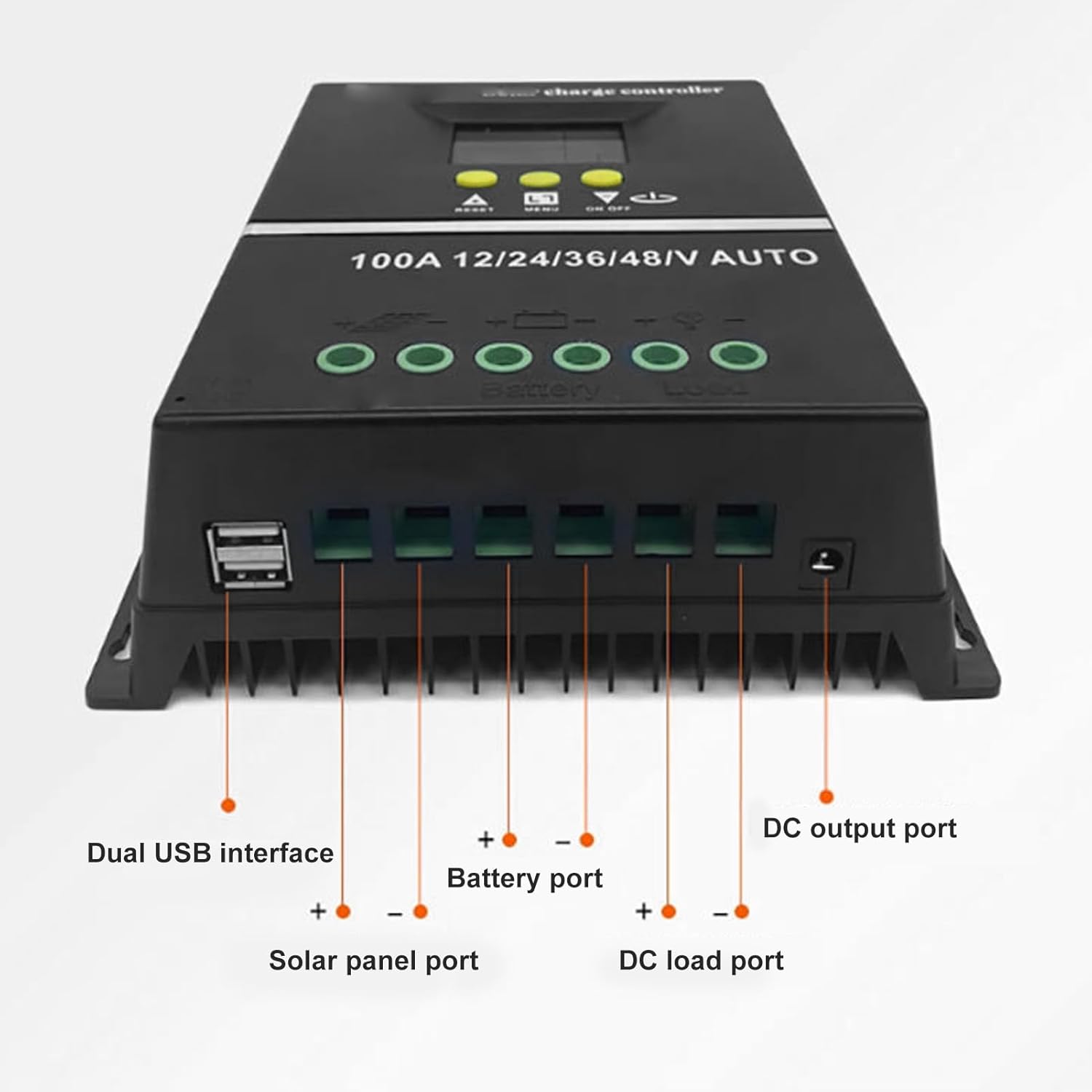
Figure 3: Bottom view showing Dual USB interface, Solar panel port, Battery port, DC load port, and DC output port.

Figure 4: Detailed view of the LCD display areas.
4. Setup and Installation
Follow these steps for proper installation of the solar charge controller:
- Prepare Wiring: Ensure all wires are of appropriate gauge for the current and length, and that they are properly stripped.
- Connect Battery: Connect the battery to the controller's battery terminals (positive to positive, negative to negative). The controller will automatically detect the system voltage (12V/24V/36V/48V).
- Connect Solar Panel: Connect the solar panel to the controller's solar panel terminals (positive to positive, negative to negative).
- Connect DC Load: Connect your DC loads to the controller's load terminals (positive to positive, negative to negative).
- Secure Connections: Double-check all connections for tightness and correct polarity.
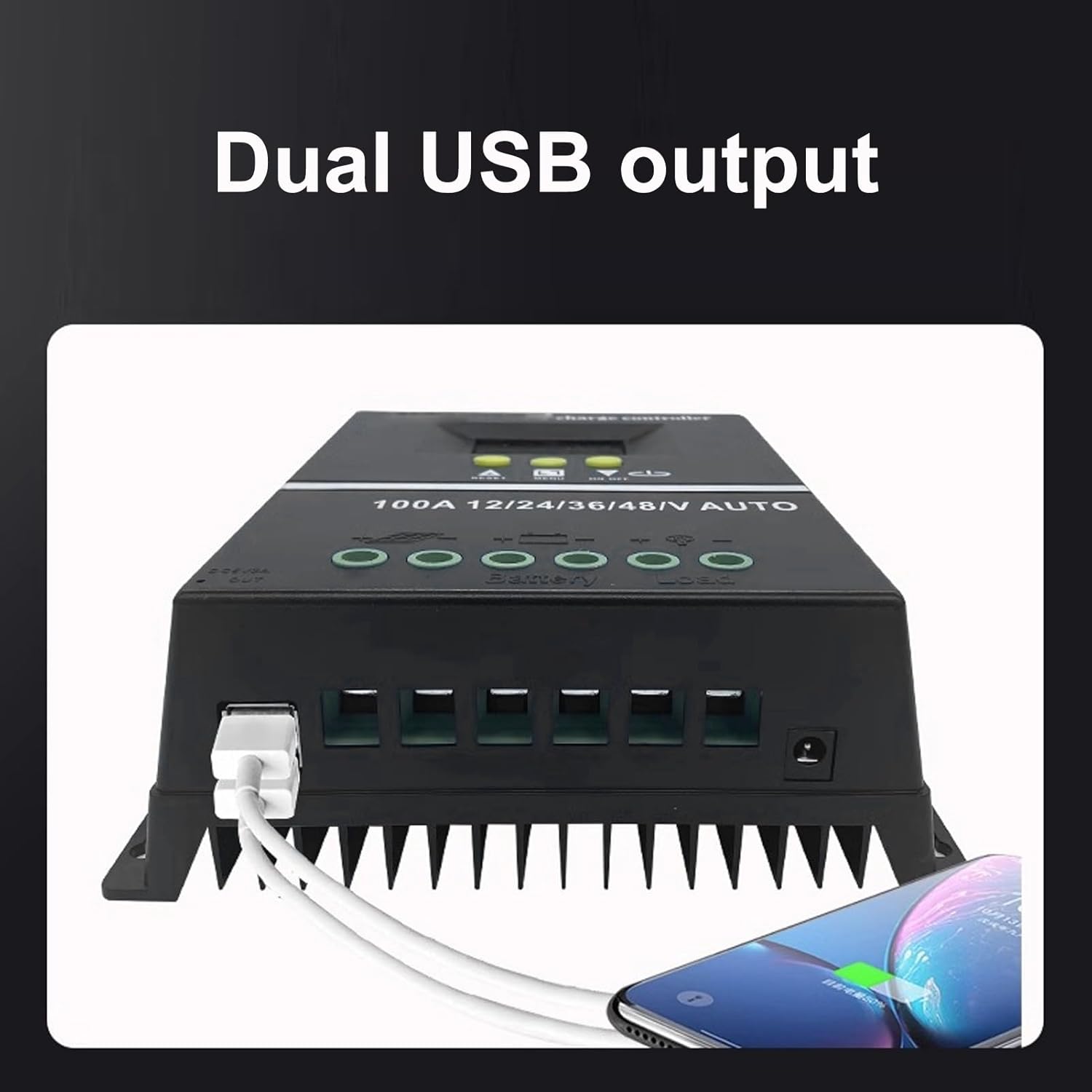
Figure 5: Connection diagram for the solar charge controller.
5. Operating Instructions
The controller features a multifunctional LCD display and several working modes to suit various applications.
5.1. LCD Display and Button Functions
The LCD dynamically displays operating data. Use the MENU button to navigate through display screens and settings. The UP/DOWN buttons (triangle symbols) adjust values or select options. The ON/OFF button controls the load output.
5.2. Working Modes
The controller offers 7 working modes:
- Charging Mode: Under no circumstances should discharge be allowed. This mode focuses solely on charging the battery.
- Light Control Mode: The controller detects night, delays for ten minutes, and then starts discharging. When it detects daytime, it delays for ten minutes and stops discharging.
- Light and Delay Control Mode: When the controller detects night, it delays for ten minutes before starting to discharge and counts down (if the timer stops at 0), the discharge will stop. The maximum delay time is 23:59.
- Universal Control Mode: Always maintains discharge without any faults.
- Manual Control Mode: Use the '▼' button to check whether to discharge.
- Timing Control Mode: Regularly turns on or off the discharge based on set times.
- Test Mode: Similar to lighting and delay control modes, but with only a ten-minute delay.
5.3. USB Charging
The dual USB 5V charging ports can be used to charge compatible electronic devices. Simply connect your device to one of the USB ports.
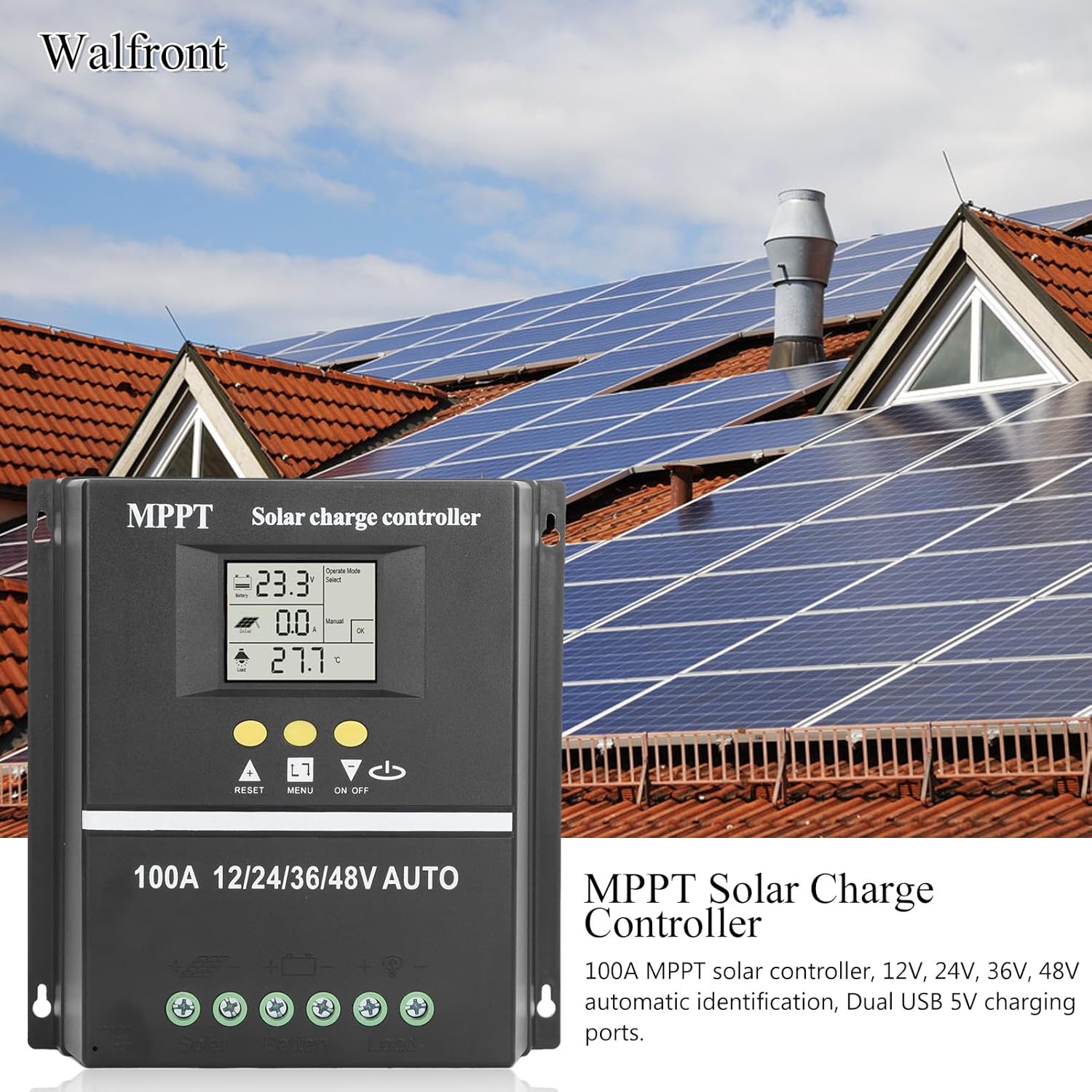
Figure 6: Using the dual USB output for charging.
6. Maintenance
Regular maintenance ensures optimal performance and longevity of your solar charge controller.
- Cleanliness: Keep the controller clean and free from dust and debris. Use a dry cloth for cleaning.
- Connections: Periodically check all wiring connections to ensure they are secure and free from corrosion.
- Ventilation: Ensure that the ventilation openings are not blocked to allow for proper heat dissipation.
- Battery Inspection: Regularly inspect your battery for any signs of damage or leakage.
7. Troubleshooting
If you encounter issues with your solar charge controller, consider the following common problems and solutions:
- No Display/No Power: Check battery connections and ensure the battery has sufficient charge. Verify all wiring is correct.
- Battery Not Charging: Check solar panel connections and ensure the panels are receiving adequate sunlight. Verify solar panel voltage is within the controller's input range.
- Load Not Working: Check load connections. Ensure the load is within the controller's rated capacity. Check if the load output is enabled (e.g., via ON/OFF button or selected working mode). The controller will stop discharge under low voltage protection.
- Error Codes on Display: Refer to the specific error code displayed on the LCD. Consult the manufacturer's support for detailed explanations and solutions for specific codes.
- Overheating: Ensure the controller is installed in a well-ventilated area and not exposed to direct sunlight or excessive ambient temperatures.
For persistent issues, please contact customer support.
8. Specifications
| Feature | Specification |
|---|---|
| Rated Current | 100A |
| System Voltage | 12V / 24V / 36V / 48V Auto Identification |
| Maximum Solar Input (Voc) | 15-23V (12V battery); 30-45V (24V battery); 45-69V (36V battery); 60-90V (48V battery) |
| Maximum Photovoltaic Input Power | 1200W (12V battery); 2400W (24V battery); 3600W (36V battery); 4800W (48V battery) |
| USB Output | Dual USB 5V |
| Display Type | LCD with backlight |
| Battery Compatibility | GEL, Flooded, LiFePO4 |
| Operating Temperature | Up to 60°C |
| Material | ABS |
| Item Weight | 1.81 pounds |
| Package Dimensions | 8.03 x 7.99 x 2.83 inches |
9. Warranty and Support
For warranty information, technical support, or service inquiries, please refer to the product packaging or contact Walfront customer service through your purchase platform. Keep your purchase receipt as proof of purchase.
