1. Introduction
This manual provides detailed instructions for the installation, operation, and maintenance of your OOYCYOO MPPT Solar Charge Controller. Please read this manual thoroughly before using the product to ensure proper function and safety.
Key Features:
- Automatic detection of 12V or 24V DC system voltages.
- Compatible with various deep cycle battery options: sealed, gel, flooded, and lithium.
- Innovative MPPT technology with high tracking efficiency up to 99% and maximum conversion efficiency of 98%.
- Electronic protection against reverse polarity, overcharge, over-discharge, short circuits, and reverse current.
- LCD screen and multiple LED indicators for displaying system operation information.
- User parameters can be reset.
- One key function to open and close the load.
- One key function to restore factory settings.
- Easy to use and program interface.

Figure 1.1: Front view of the OOYCYOO MPPT Solar Charge Controller, showing the LCD display and control buttons.
2. Package Contents
Please check the package contents upon unpacking. If any items are missing or damaged, contact your retailer.
- 1 x OOYCYOO MPPT Solar Charge Controller
- 1 x Temperature Sensor
- 1 x English User Manual
3. Safety Information
Please observe the following safety precautions during installation and operation:
- Ensure all wiring is correctly polarized and securely connected to prevent damage to the controller or other components.
- Do not exceed the maximum input voltage or current ratings of the controller.
- Install the controller in a well-ventilated area, away from flammable materials and direct sunlight.
- Avoid contact with water or other liquids.
- Do not attempt to disassemble or repair the controller yourself. Refer to qualified personnel for service.
- Always disconnect power from the solar panel and battery before performing any maintenance or wiring.
- Wear appropriate personal protective equipment (PPE) such as gloves and eye protection during installation.
4. Product Overview
The OOYCYOO MPPT Solar Charge Controller features a clear LCD display and various terminals for connecting your solar power system components. Refer to the diagram below for an overview of the controller's parts.

Figure 4.1: Labeled components of the OOYCYOO MPPT Solar Charge Controller.
Component Descriptions:
- LCD Display: Shows real-time system data, operating status, and settings.
- 5S Reset Button: Used to restore factory settings by long-pressing for 5 seconds.
- Solar Panel Terminal: Connects to the positive and negative terminals of your solar panel array.
- Battery Terminal: Connects to the positive and negative terminals of your battery bank.
- Load Terminal: Connects to the positive and negative terminals of your DC load.
- 2*USB 5V 2.4A Ports: Provides 5V DC power for charging USB devices.
- Remote Temp Sensor Port: Connects the included temperature sensor for accurate battery temperature compensation.
- Select Button: Used to navigate through menu options and confirm selections.
- RS485 Communication Port: For advanced communication and monitoring (requires additional purchase of compatible display/module).
- Mounting Holes: Five holes for secure installation of the controller.
5. Setup and Installation
Follow these steps for proper installation of your MPPT solar charge controller. Adhering to the connection order is critical to prevent damage.
Connection Diagram:
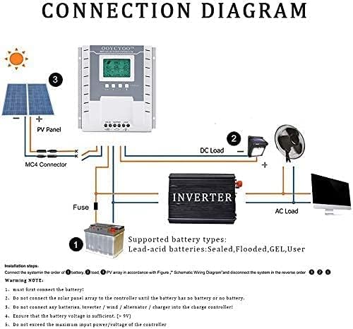
Figure 5.1: Schematic wiring diagram for the solar charge controller system.
Installation Steps:
- Mounting: Securely mount the controller to a flat, vertical surface using the five mounting holes. Ensure adequate ventilation around the unit.
- Connect Battery: First, connect the battery to the controller's Battery Terminal (positive to positive, negative to negative). Ensure the battery voltage is sufficient (greater than 9V). The controller will automatically detect 12V or 24V system voltage.
- Connect DC Load: Next, connect your DC load to the controller's Load Terminal (positive to positive, negative to negative).
- Connect Solar Panel: Finally, connect the solar panel array to the controller's Solar Panel Terminal (positive to positive, negative to negative). Do not connect the solar panel array until the battery is properly connected.
- Connect Temperature Sensor: Plug the included temperature sensor into its dedicated port. This ensures accurate battery charging based on ambient temperature.
- Verify Connections: Double-check all connections for polarity and tightness before powering on the system.
Important Notes:
- Always connect the battery first and disconnect the solar panel first when disassembling the system.
- Do not connect any other charging sources (e.g., inverters, wind alternators, or other chargers) directly to the charge controller's terminals.
- Ensure that the maximum input power and voltage from the solar panels do not exceed the controller's specifications.
Supported Battery Types:
The controller is compatible with the following lead-acid battery types:
- Sealed
- Flooded
- GEL
- User-defined (for custom settings)
6. Operating Instructions
The OOYCYOO MPPT Solar Charge Controller features an intuitive LCD display for monitoring system status and adjusting settings.
LCD Display Overview:

Figure 6.1: Detailed view of the LCD display and button functions.
The LCD display provides real-time data on a single screen, allowing for convenient monitoring of your system. Key indicators include:
- PV (Solar Panel) Voltage and Amperage: Current output from your solar panels.
- Battery Voltage and Amperage: Current battery charge status and current flow.
- Load Voltage and Amperage: Power consumption of your connected DC load.
- Battery Capacity: Percentage of battery charge.
- Charging/Discharging Fault Indicators: Alerts for system issues.
- Evening/Dawn Status: Indicates day/night cycle for load control.
- Load Stop Working Hours: Configured hours for load operation.
- Float Charging Voltage: Voltage at which the battery is maintained after full charge.
- Low Voltage Disconnect/Reconnect Voltage: Thresholds for battery protection.
Button Functions:
- Toggle Key (Left Arrow): Used to cycle through different display screens or menu options.
- "+" Button: Increases values or moves forward in menu settings.
- "-" Button: Decreases values or moves backward in menu settings.
- Light Bulb / Manual Load Switch Button: This button can be used to manually open or close the DC load.
- 5S Reset Button: Long press and hold this button for 5 seconds to restore the controller to its factory default settings.
- Troubleshooting/Eliminate 'X' Button: If an 'X' error or system failure is displayed, click this button to attempt troubleshooting or clear the error.
Network Line Interface (RS485) Indicator:
- Green Light: Represents the battery status.
- Green Light Flashes: Indicates that the load is working properly.
- Yellow Light: Indicates solar energy availability.
- Yellow Light Flashes: Indicates active solar charging.
- The network interface is reserved for the interface and can be connected to a dedicated display (additional purchase).
7. Maintenance
Regular maintenance ensures the longevity and optimal performance of your solar charge controller.
- Cleaning: Periodically clean the controller's exterior with a dry, soft cloth. Do not use abrasive cleaners or solvents. Ensure ventilation openings are free from dust and debris.
- Connection Checks: Annually inspect all wiring connections for tightness and corrosion. Loose connections can lead to power loss or overheating.
- Environmental Conditions: Ensure the controller remains within its specified operating temperature and humidity ranges. Protect it from direct sunlight, rain, and excessive dust.
- Battery Health: Monitor your battery's health and voltage regularly. Ensure it is not overcharged or deeply discharged, as this can shorten its lifespan.
8. Troubleshooting
If you encounter issues with your OOYCYOO MPPT Solar Charge Controller, refer to the following common problems and solutions:
| Problem | Possible Cause | Solution |
|---|---|---|
| Controller not powering on / LCD blank | No battery connected or battery voltage too low. Reverse polarity connection. Loose battery connection. | Ensure battery is connected first and has sufficient voltage (>9V). Check battery polarity. Tighten battery terminal connections. |
| No charging current from solar panels | Solar panel not connected. Reverse polarity of solar panel. Insufficient sunlight. PV input voltage too low/high. | Connect solar panels. Check PV polarity. Ensure adequate sunlight. Verify PV voltage is within specifications (18-96V for 12V system, 36-96V for 24V system). |
| Load not working | Load not connected. Load switch off. Battery voltage too low (low voltage disconnect). Overload/short circuit on load. | Connect load. Press the manual load switch button. Charge battery. Reduce load or check for short circuits. |
| Error 'X' displayed on LCD | System fault or specific error code. | Press the 'X' button to attempt troubleshooting or clear the error. Refer to the manual for specific error code meanings if available. If persistent, contact support. |
| Inaccurate temperature readings | Temperature sensor not connected or faulty. | Ensure the temperature sensor is securely plugged in. Replace if faulty. |
9. Technical Specifications
The following table outlines the technical specifications of the OOYCYOO MPPT Solar Charge Controller (Model K):
| Parameter | Value |
|---|---|
| Model | MPPT 40A |
| System Voltage | 12V / 24V Auto-detection |
| Max Power Current | 40A |
| Max PV Input Voltage (Voc) | 18V ~ 96V (12V system) 36V ~ 96V (24V system) Overall Max: ≤ 96V |
| Max Solar Panel Power (Wp) | 520W (12V system) 1040W (24V system) |
| Battery Capacity Configuration | Up to 300 Ah |
| Battery Float Voltage | 13.8V (12V system) 27.6V (24V system) |
| Battery Protection (Undervoltage) | 10.6V (12V system) 21.2V (24V system) |
| Battery Recovery Voltage (Undervoltage) | 12.6V (12V system) 25.2V (24V system) |
| System No-Load Loss | ≤ 13 mA |
| Buck Loop Drop | ≤ 100 mV |
| Operating Temperature | -10 °C ~ 60 °C |
| Storage Temperature | -30 °C ~ -70 °C |
| Operating Humidity | ≤ 90%, non-condensing |
| Temperature Compensation | -4 mV/cell/°C |
| Display Type | LCD |
| Installation Wire Size (mm²) | 12 mm² |
| Installation Wire Size (AWG) | 8 # (AWG) |
| Dimensions (L x W x H) | 21 x 20.9 x 8.4 cm |
| Weight | 1.24 Kilograms |
| Material | Plastic |
| Color | White |
| UPC | 768561407224 |
| ASIN | B0CW6468P2 |
10. Warranty and Support
For warranty information and technical support, please refer to the documentation provided with your purchase or contact your retailer. Keep your proof of purchase for warranty claims.
If you require further assistance or have questions not covered in this manual, please reach out to OOYCYOO customer support through the contact information provided on the product packaging or the official OOYCYOO website.


