1. Introduction
This manual provides detailed instructions for the safe and effective operation, setup, maintenance, and troubleshooting of your TEMPO Communications 521E Wire and Sprinkler Valve Locator Tool. Please read this manual thoroughly before using the device to ensure proper functionality and to prevent damage or injury.
2. Safety Information
Always observe the following safety precautions when using the 521E locator tool:
- Read all instructions: Familiarize yourself with the operation and safety guidelines before use.
- Battery Safety: Use only the specified battery types and ensure correct polarity. Do not mix old and new batteries. Remove batteries if the unit will not be used for an extended period.
- Electrical Hazard: The transmitter generates a signal. Avoid connecting the transmitter leads to live electrical circuits. Always ensure the circuit is de-energized before connecting the transmitter.
- Environmental Conditions: Do not operate the device in explosive atmospheres or near flammable liquids or gases. While the unit is water-resistant, avoid submerging it.
- Personal Protective Equipment: Wear appropriate personal protective equipment (PPE) such as gloves and safety glasses when working in outdoor environments or digging.
- Proper Handling: Handle the equipment with care. Do not drop or subject it to excessive force.
3. Package Contents
Verify that all components are present in your 521E package:
- 521-T Transmitter
- 521E-R Receiver
- HS-1 Headset
- 521E-C Carry Case
- Ground Stake
- Connection Leads

Figure 3.1: All components of the TEMPO 521E Wire and Sprinkler Valve Locator Tool, including the transmitter, receiver, headset, and carry case.
4. Setup
4.1. Battery Installation
The 521E system requires batteries for both the transmitter and receiver. Batteries are not included.
- Transmitter (521-T): Requires six (6) 1.5V D-cell alkaline batteries. Open the battery compartment on the underside of the transmitter and insert the batteries, observing correct polarity.
- Receiver (521E-R): Requires four (4) 1.5V AA-cell alkaline batteries. Open the battery compartment on the handle of the receiver and insert the batteries, observing correct polarity.

Figure 4.1: The 521E Transmitter with its battery compartment visible. Ensure correct battery orientation.
4.2. Receiver Assembly
Attach the carbon fiber reinforced rod to the receiver handle by screwing it into the designated port until secure.

Figure 4.2: The 521E Receiver with the carbon fiber rod attached.
4.3. Connecting the Transmitter
The transmitter sends a signal through the wire you wish to locate. Connect the transmitter leads as follows:
- Connect the red lead to the wire you want to trace.
- Connect the black lead to a good ground source, such as a metal stake driven into the earth, a cold water pipe, or the neutral wire of a power source (if safe and appropriate for the application).
- Ensure all connections are secure to establish a clear signal path.

Figure 4.3: Proper connection of the transmitter leads to the target wire and ground.
5. Operation
The 521E locator tool is designed for accurate and efficient tracing of buried wires, irrigation valves, and cable faults.
5.1. Powering On and Signal Adjustment
- Turn on both the transmitter and receiver. The large, sunlight-compatible LCD displays will illuminate.
- Adjust the signal level on the transmitter as needed. A higher signal level may be required for deeper or longer wires.
- Connect the HS-1 Headset to the receiver for clearer audio feedback, especially in noisy environments.
5.2. Wire Tracing
To trace a buried wire:
- With the transmitter connected and powered on, hold the receiver with the carbon fiber rod pointing towards the ground.
- Walk slowly along the suspected path of the wire. The receiver will provide visual and audio indications of the signal strength.
- The signal will be strongest directly over the buried wire. Follow the path where the signal is maximized. The receiver's ergonomic design allows for comfortable one-handed operation.
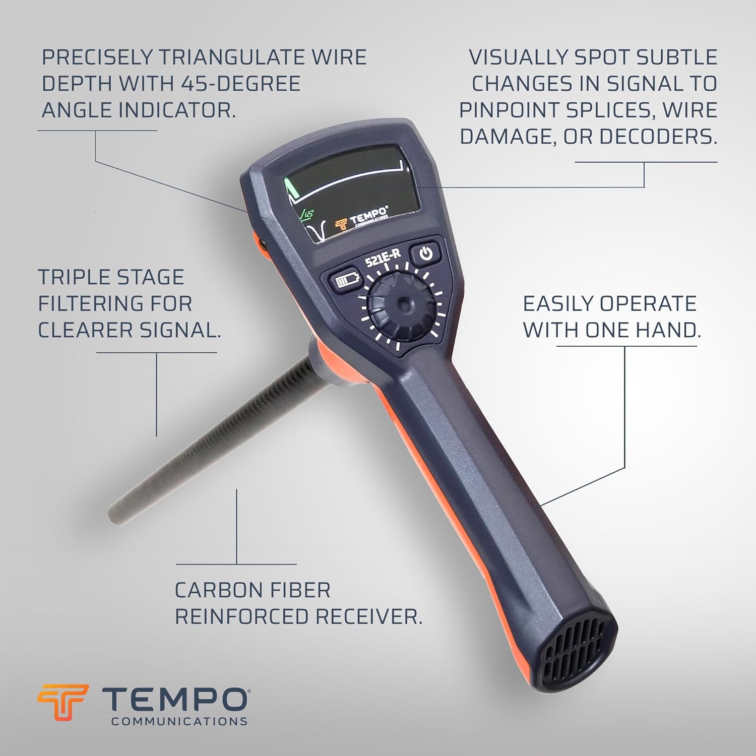
Figure 5.1: Demonstrating the use of the 521E Receiver for wire tracing.
5.3. Depth Determination
The 521E features a 45-degree angle indicator for determining wire depth:
- Once the wire path is located, hold the receiver at a 45-degree angle to the ground, directly over the wire.
- The 45-degree angle indicator on the display will light up when the receiver is within 3 degrees of the correct angle.
- The depth of the wire can then be triangulated within 10% accuracy.
5.4. Fault Finding and Valve Location
The 521E is effective for locating underground wire breaks, large nicks, and solenoid valves:
- When tracing a wire, a sudden drop or loss of signal can indicate a break or fault.
- For valve location, trace the control wire to the area where the valve is suspected. The signal will often change or become more localized directly over the valve.
- The receiver's triple-stage filtering helps provide a clearer signal, allowing for visual identification of subtle signal changes to pinpoint splices, wire damage, or decoders.
6. Maintenance
6.1. Battery Replacement
The typical battery life for both the transmitter and receiver is approximately 50 hours. Replace batteries promptly when the low battery indicator appears on the display to ensure optimal performance.
6.2. Cleaning and Storage
- Clean the exterior of the unit with a damp cloth. Do not use abrasive cleaners or solvents.
- Ensure the unit is dry before storing.
- Store the 521E in its carry case in a cool, dry place, away from direct sunlight and extreme temperatures.
- Remove batteries if the unit will not be used for an extended period to prevent leakage.
7. Troubleshooting
If you encounter issues with your 521E locator tool, refer to the following common problems and solutions:
| Problem | Possible Cause | Solution |
|---|---|---|
| Unit does not power on | Dead or incorrectly installed batteries. | Check battery polarity and ensure batteries are fresh. Replace if necessary. |
| Weak or no signal detected | Poor transmitter connection, low transmitter battery, wire too deep, or signal interference. | Ensure transmitter leads are securely connected to the target wire and a good ground. Replace transmitter batteries. Increase transmitter signal level. Reduce interference from other electrical sources. |
| Inaccurate wire tracing or depth readings | Improper technique, environmental factors (e.g., wet soil, metallic objects), or signal interference. | Review operation instructions for proper tracing and depth determination techniques. Be aware of surrounding metallic objects. Practice in a known area. |
| Intermittent signal or erratic readings | Loose connections, damaged wire, or strong external electrical noise. | Check all connections. Inspect the wire for visible damage. Move away from known sources of electrical interference. |
8. Specifications
| Feature | Specification |
|---|---|
| Model | 521E (2025 Model) |
| Manufacturer | Tempo Communications |
| Part Number | 521E |
| Item Weight | 10.13 pounds |
| Product Dimensions | 28 x 12.58 x 4.1 inches |
| Color | Orange |
| Material | Plastic |
| Power Source | Battery Powered |
| Transmitter Batteries | 6 D cells (alkaline recommended) |
| Receiver Batteries | 4 AA cells (alkaline recommended) |
| Wattage | 2500 Milliwatts |
| Transmitter Frequency | 1750 Hz |
| Transmitter Power | 2500 mW into 1 kohm |
| Battery Life | Transmitter: 50 hours nominal Receiver: 50 hours nominal |
| Automatic Shut-off | 1.5 hours |

Figure 8.1: Official specifications and product features for the 521E.
9. Support
For technical assistance, warranty information, or customer service, please contact Tempo Communications directly:
- Website: Tempo Communications Store
- Phone: 800.642.2155 (as per spec sheet image)
- Email: sales@tempocom.com (as per spec sheet image)
- Address: Tempo Headquarters, 1390 Aspen Way, Vista, CA 92081, USA (as per spec sheet image)


