1. Introduction
The GeRRiT 5069-RTB6-SCREW is a robust 6-pole screw terminal block designed for reliable electrical connections within industrial automation control systems. This component is engineered to ensure system stability and safety in demanding environments. Its design facilitates quick installation and straightforward maintenance, contributing to enhanced operational efficiency.
This terminal block is an ideal accessory for various industrial automation applications, including PLC (Programmable Logic Controller), AC Drive, and Industry Panel systems, providing precise signal transmission.

Figure 1: Front view of the 5069-RTB6-SCREW terminal block, highlighting the six individual screw terminals for wire connections.
2. Setup and Installation
Proper installation of the 5069-RTB6-SCREW is crucial for optimal performance and safety. Follow these steps carefully:
- Preparation: Ensure all power to the control system is disconnected before beginning installation. Verify that the wiring meets local electrical codes and system requirements.
- Mounting: The terminal block is designed for secure attachment to compatible industrial control modules. Align the mounting features of the 5069-RTB6-SCREW with the corresponding slots on the module.
- Secure Connection: Gently push the terminal block into place until it clicks or is firmly seated. Ensure there is no wobble or loose connection.
- Wiring: Using appropriate wire gauges for your application, strip approximately 7-9mm (0.28-0.35 inches) of insulation from each wire end. Insert the stripped wire into the designated screw terminal opening.
- Tightening Screws: Use a suitable screwdriver to tighten the terminal screws. Ensure the screws are tightened sufficiently to create a secure electrical connection, but do not overtighten, as this can damage the terminal block or wires. Refer to system documentation for specific torque requirements if available.
- Verification: After wiring all connections, visually inspect each terminal to confirm wires are properly seated and screws are tight.

Figure 2: Top view illustrating the screw terminals ready for wire insertion and tightening.
3. Operating Principles
The 5069-RTB6-SCREW functions as an interface for connecting field devices and sensors to industrial control modules. Each of the six screw terminals provides a secure point for electrical signal transmission.
- Signal Integrity: The copper material and robust screw mechanism ensure low resistance and high signal integrity, critical for precise control applications.
- Polarity: Observe any polarity markings (+/-) on the terminal block or associated module when making connections to ensure correct circuit operation.
- Current and Voltage Ratings: Always operate the terminal block within the specified current and voltage ratings of the connected industrial control module to prevent damage and ensure safety.

Figure 3: Side view displaying the model number and manufacturing information, essential for identification and compliance.
4. Maintenance
The 5069-RTB6-SCREW is designed for minimal maintenance. However, periodic checks are recommended to ensure continued reliable operation:
- Visual Inspection: Regularly inspect the terminal block for any signs of physical damage, discoloration, or loose connections.
- Connection Integrity: In environments subject to vibration or significant temperature fluctuations, periodically re-check the tightness of the screw terminals to prevent signal loss or intermittent operation.
- Cleaning: If necessary, gently clean the exterior of the terminal block with a dry, lint-free cloth. Do not use abrasive cleaners or solvents. Ensure power is disconnected before cleaning.
5. Troubleshooting
If you encounter issues with the 5069-RTB6-SCREW, consider the following troubleshooting steps:
| Problem | Possible Cause | Solution |
|---|---|---|
| Intermittent signal / No signal | Loose wire connection; Damaged wire; Incorrect wiring; Module fault. | Verify all screw terminals are tight. Inspect wires for damage and replace if necessary. Confirm wiring matches system diagrams. Test the connected module. |
| Terminal block does not seat properly | Misalignment; Obstruction; Incompatible module. | Ensure correct orientation and alignment. Check for debris in the module's slot. Verify compatibility with the specific industrial control module. |
| Overheating / Discoloration | Overcurrent; Loose connection; Environmental factors. | Immediately disconnect power. Check system current draw against specifications. Re-tighten connections. Ensure adequate ventilation in the enclosure. Consult a qualified technician. |
If troubleshooting steps do not resolve the issue, contact GeRRiT customer support or a qualified industrial automation technician.
6. Specifications
The following table details the key specifications for the GeRRiT 5069-RTB6-SCREW:
| Attribute | Value |
|---|---|
| Model Number | 5069-RTB6-SCREW |
| Brand | GeRRiT |
| Connector Type | Screw Terminal Block |
| Number of Poles | 6 |
| Material | Copper (terminals) |
| Color | One Color (typically grey) |
| Package Dimensions | 1.18 x 0.79 x 0.39 inches (30 x 20 x 10 mm) |
| Item Weight | 1.76 ounces (50 grams) |
| Manufacturer | Industrial Control Boutique |
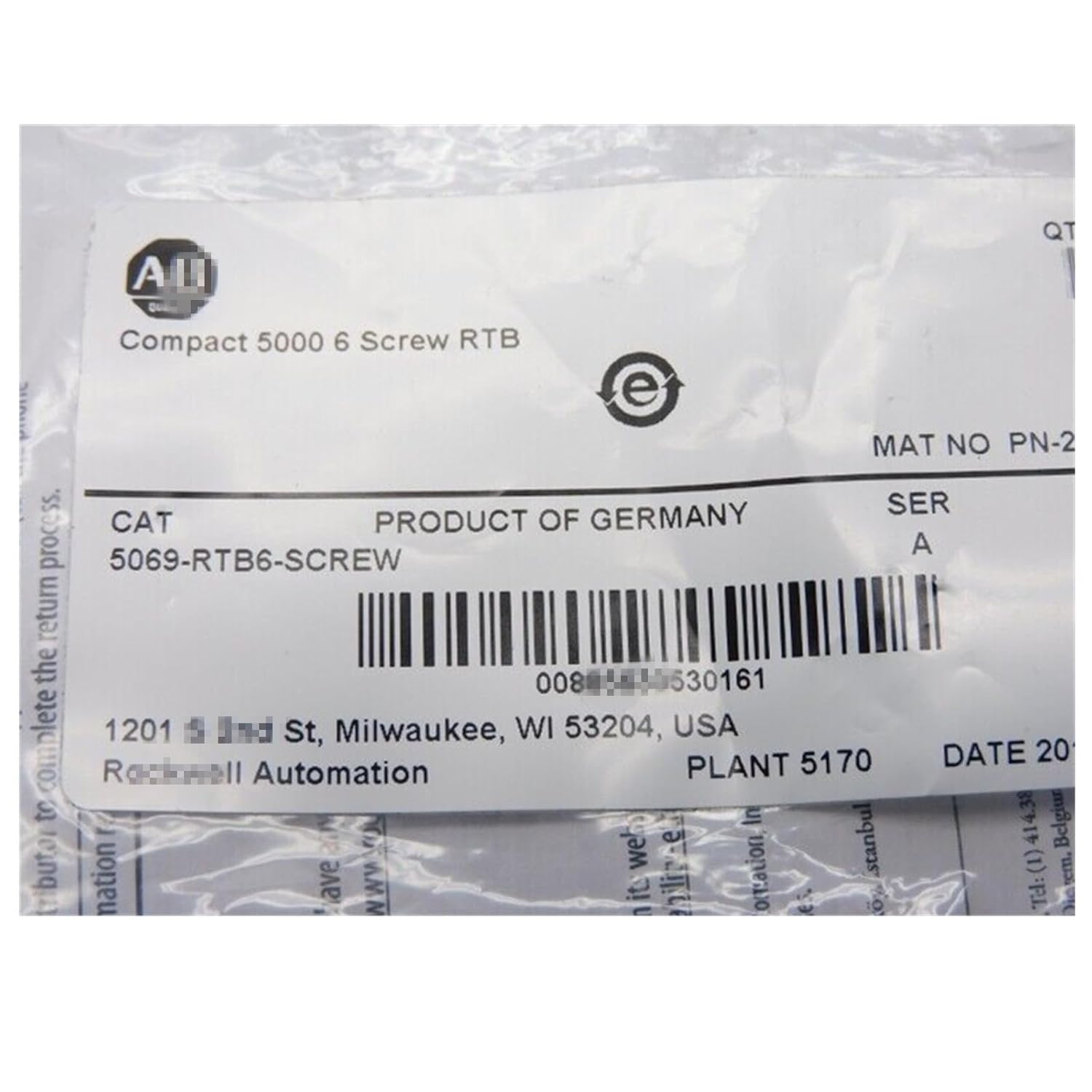
Figure 4: Product packaging label confirming the model number and manufacturing details.
Relevant link extracted from image: GTIN: 00885630530161
7. Warranty Information
The GeRRiT 5069-RTB6-SCREW comes with a one-year warranty from the date of purchase. This warranty covers defects in materials and workmanship under normal use and service. It does not cover damage resulting from improper installation, misuse, unauthorized modification, or external causes such as accidents or power surges.
For warranty claims, please retain your proof of purchase and contact customer support.
8. Customer Support
For technical assistance, product inquiries, or warranty support, please contact Industrial Control Boutique, the manufacturer and seller of this product. Their dedicated professionals are available to assist with any questions regarding industrial automation modules.
You can typically find contact information on the seller's page on the platform where the product was purchased, or through their official website.
Online Support: Industrial Control Boutique Seller Page


