1. Safety Information
Please read and understand all safety information and operating instructions before using this instrument. Failure to follow these instructions could result in electric shock, fire, or serious injury.
- General Safety: Always use the correct function and range for measurements. Do not exceed the maximum input values specified for each range.
- Personal Protective Equipment: Always wear appropriate personal protective equipment (PPE), such as safety glasses and insulated gloves, when working with electrical circuits.
- Live Circuits: Never touch live circuits with bare hands or uninsulated tools. Assume all circuits are live until proven otherwise.
- Probe Connection: Connect the common (COM) test lead first, then the live test lead. Disconnect the live test lead first, then the common test lead.
- Battery Check: Replace batteries immediately when the low battery indicator appears to ensure accurate readings and proper operation.
- Environmental Conditions: Do not use the device in wet environments or in the presence of explosive gases or dust.
- Damage Inspection: Before each use, inspect the device and test leads for any damage. Do not use if damaged.
- Non-Contact Voltage Tester: The NCV function is for indication only. Always verify voltage presence or absence with a contact method before working on circuits.
2. Product Overview
The KAIWEETS HT118A Digital Multimeter and HT100s Non-Contact Voltage Tester are versatile tools designed for electrical measurements and safety checks. The HT118A multimeter offers a wide range of functions for professional and home use, while the HT100s provides a convenient and safe way to detect AC voltage without direct contact.

Figure 2.1: KAIWEETS HT118A Digital Multimeter and HT100s Non-Contact Voltage Tester. This image displays both the digital multimeter on the left and the non-contact voltage tester on the right, showcasing their overall design and key features.
2.1. KAIWEETS HT118A Digital Multimeter Features
- True RMS (TRMS): Provides accurate readings for non-sinusoidal waveforms.
- 6000 Counts Display: High-resolution display for precise measurements.
- Auto-Ranging: Automatically selects the correct measurement range, simplifying operation.
- Wide Measurement Capabilities: Measures AC/DC Voltage (up to 600V), AC/DC Current (up to 10A), Resistance (up to 60 MOhms), Capacitance, Frequency, Duty Cycle, Temperature, Diode, and Continuity.
- LED Lightning Jacks: Flashing LED lights on the input jacks guide correct test lead placement.
- Large Backlit LCD Display: 2.9-inch HTN backlit screen for easy readability in various lighting conditions.
- Data Hold (HOLD): Freezes the displayed reading.
- Maximum/Minimum (MAX/MIN): Records the highest and lowest readings.

Figure 2.2: KAIWEETS HT118A Multimeter Functions and Battery Compartment. This image highlights the various measurement functions available on the multimeter's rotary dial and shows the rear battery compartment.
2.2. KAIWEETS HT100s Non-Contact Voltage Tester Features
- Non-Contact AC Voltage Detection (NCV): Detects AC voltage without physical contact.
- Dual Range Sensitivity: Detects standard (70-1000V AC) and low voltage (12-1000V AC) for diverse applications.
- Live/Null Wire Detection: Automatically identifies live or neutral wires.
- Visual and Audible Alarms: Provides sound and light indications for voltage presence and intensity.
- Breakpoint Test: Useful for identifying breaks in insulated wires.
- Integrated LED Flashlight: Assists in working in dimly lit areas.
3. Setup
3.1. Battery Installation
Both the HT118A Multimeter and HT100s Voltage Tester require batteries for operation.
- Ensure the device is powered off.
- Locate the battery compartment cover on the back of the device.
- Use a screwdriver (if necessary) to open the battery compartment.
- Insert the required batteries, observing the correct polarity (+/-).
- Securely close the battery compartment cover.
3.2. Test Lead Connection (HT118A Multimeter)
For most measurements, connect the test leads as follows:
- Insert the black test lead into the "COM" (Common) jack.
- Insert the red test lead into the "VΩmA" jack for voltage, resistance, and small current measurements.
- For current measurements up to 10A, insert the red test lead into the "10A" jack.

Figure 3.1: KAIWEETS HT118A Multimeter LED Lightning Jacks. This image shows the multimeter's input jacks with LED lights, which illuminate to guide the user to the correct probe connection point for the selected function.
4. Operating Instructions
4.1. KAIWEETS HT118A Digital Multimeter Operation
Turn the rotary dial to select the desired measurement function. The multimeter features auto-ranging, which automatically selects the appropriate measurement range.

Figure 4.1: KAIWEETS HT118A Multimeter 2.9-inch Backlit Screen. This image displays the multimeter's large, backlit LCD screen showing a measurement, emphasizing its readability and dual reading capability.
4.1.1. Voltage Measurement (AC/DC)
- Set the rotary dial to the "V~" (AC Voltage) or "V-" (DC Voltage) position.
- Connect the black test lead to the "COM" jack and the red test lead to the "VΩmA" jack.
- Carefully touch the test probes to the circuit points where voltage is to be measured (in parallel with the load).
- Read the voltage value on the display.
4.1.2. Current Measurement (AC/DC)
Caution: Always connect the multimeter in series with the circuit when measuring current. Never connect it in parallel with a voltage source.
- Set the rotary dial to the "A~" (AC Current) or "A-" (DC Current) position. For small currents, use the "mA" or "μA" range.
- Connect the black test lead to the "COM" jack. Connect the red test lead to the "10A" jack for currents up to 10A, or to the "VΩmA" jack for mA/μA measurements.
- Open the circuit where current is to be measured and connect the test probes in series.
- Read the current value on the display.
4.1.3. Resistance Measurement
Caution: Ensure the circuit is de-energized before measuring resistance. Disconnect power to the component being tested.
- Set the rotary dial to the "Ω" (Resistance) position.
- Connect the black test lead to "COM" and the red test lead to "VΩmA".
- Touch the test probes across the component to be measured.
- Read the resistance value on the display.
4.1.4. Continuity Test
- Set the rotary dial to the "Continuity" position (often shared with Diode/Resistance).
- Connect the black test lead to "COM" and the red test lead to "VΩmA".
- Touch the test probes to the two points of the circuit or component.
- If continuity exists (low resistance), the multimeter will emit an audible beep.
4.1.5. Diode Test
- Set the rotary dial to the "Diode" position (often shared with Continuity/Resistance).
- Connect the black test lead to "COM" and the red test lead to "VΩmA".
- Touch the red probe to the anode and the black probe to the cathode of the diode.
- The display will show the forward voltage drop. Reverse the probes; an open circuit (OL) reading indicates a good diode.
4.1.6. Capacitance Measurement
Caution: Discharge capacitors before testing to prevent damage to the multimeter.
- Set the rotary dial to the "Capacitance" position.
- Connect the black test lead to "COM" and the red test lead to "VΩmA".
- Touch the test probes across the capacitor terminals.
- Read the capacitance value on the display.
4.1.7. Frequency and Duty Cycle Measurement
- Set the rotary dial to the "Hz%" (Frequency/Duty Cycle) position.
- Connect the black test lead to "COM" and the red test lead to "VΩmA".
- Connect the test probes to the signal source.
- Read the frequency (Hz) or duty cycle (%) on the display. Use the "FUNC" button to switch between modes if necessary.
4.1.8. Temperature Measurement
The HT118A supports temperature measurement using a K-Type thermocouple.
- Set the rotary dial to the "°C/°F" (Temperature) position.
- Connect the K-Type thermocouple to the appropriate input jacks (usually marked for temperature).
- Place the thermocouple tip on or near the object whose temperature is to be measured.
- Read the temperature value on the display.

Figure 4.2: KAIWEETS HT118A Multimeter Temperature Measurement. This image illustrates the multimeter measuring the temperature of a liquid using the included K-Type thermocouple.
4.2. KAIWEETS HT100s Non-Contact Voltage Tester Operation
The HT100s allows for quick and safe detection of AC voltage without direct contact.
4.2.1. Basic NCV Detection
- Press the power button to turn on the HT100s.
- Place the tip of the tester near a terminal strip, outlet, or insulated wire.
- If AC voltage is detected, the tip will glow red, and the tester will emit an audible beep. The frequency of the beep and the percentage value on the screen will increase with stronger voltage signals.

Figure 4.3: KAIWEETS HT100s NCV Tester in use on an outlet. This image shows the non-contact voltage tester being used to detect voltage in an electrical outlet, with the tip glowing red.
4.2.2. Sensitivity Adjustment (Dual Range)
The HT100s offers two sensitivity modes:
- High Sensitivity Mode (12-1000V AC): Suitable for detecting lower voltages, such as those in doorbells, thermostats, or irrigation wiring.
- Low Sensitivity Mode (70-1000V AC): Standard mode for detecting higher voltages in typical household wiring.
Press the "S" button to switch between high and low sensitivity modes. The display will indicate the current mode.
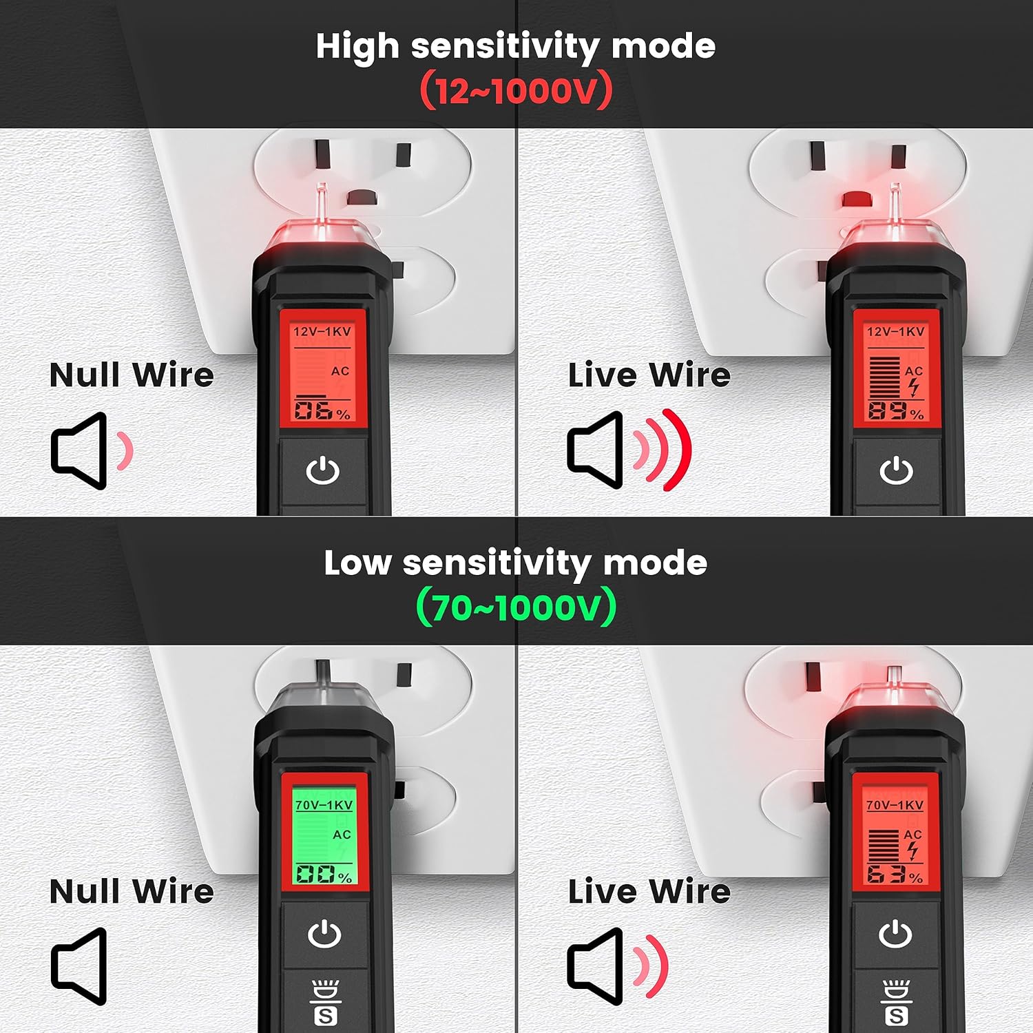
Figure 4.4: KAIWEETS HT100s NCV Tester High and Low Sensitivity Modes. This image demonstrates the difference in detection for null and live wires under both high (12-1000V) and low (70-1000V) sensitivity settings.
4.2.3. Live/Null Wire Detection
When detecting voltage, the screen will display red for a live wire (high voltage) and green for a null (neutral) wire (low voltage). This provides a quick visual indication of wire status.
4.2.4. Breakpoint Test
To perform a breakpoint test, run the NCV tester along an insulated wire. The tester will indicate voltage up to the point of a break in the wire, where the signal will cease.

Figure 4.5: KAIWEETS HT100s NCV Tester Breakpoint Test. This image shows the NCV tester being used to identify a break in an insulated electrical cable by detecting the presence or absence of voltage along its length.
4.2.5. LED Flashlight
Press the flashlight button to activate the integrated LED flashlight, useful for illuminating work areas in low-light conditions.

Figure 4.6: KAIWEETS HT100s NCV Tester with LED Flashlight. This image shows the NCV tester's tip illuminating a dark electrical panel with its built-in LED flashlight.
5. Maintenance
5.1. Cleaning
Wipe the device with a damp cloth and mild detergent. Do not use abrasive cleaners or solvents. Ensure the device is completely dry before storage or next use.
5.2. Battery Replacement
When the low battery indicator appears on the display, replace the batteries immediately to maintain measurement accuracy. Refer to Section 3.1 for battery installation instructions.
5.3. Storage
If the device is not used for an extended period, remove the batteries to prevent leakage. Store the device in a cool, dry place, away from direct sunlight and extreme temperatures.
6. Troubleshooting
- Device does not power on: Check battery installation and ensure batteries are not depleted. Replace if necessary.
- Inaccurate readings: Ensure test leads are properly connected. Check battery level. Verify the correct function and range are selected.
- No NCV detection: Ensure the device is powered on. Check sensitivity settings (high/low). Ensure the tip is close enough to the voltage source.
- Continuity test not beeping: Ensure the circuit is de-energized. Check for actual continuity in the component.
7. Specifications
| Feature | Specification |
|---|---|
| Brand | KAIWEETS |
| Model | HT118A (Multimeter), HT100s (Voltage Tester) |
| Display | 6000 Counts, 2.9" HTN Backlit LCD |
| AC/DC Voltage | Up to 600V |
| AC/DC Current | Up to 10A |
| Resistance | Up to 60 MΩ |
| Capacitance | Yes |
| Frequency/Duty Cycle | Yes |
| Temperature | Yes (K-Type Thermocouple) |
| Continuity Test | Yes (with audible beep) |
| Diode Test | Yes |
| NCV Detection Range | 12-1000V AC / 70-1000V AC (Dual Range) |
| Power Source | Battery Powered |
| Safety Rating | CAT III 600V (HT118A) |
8. Warranty and Support
KAIWEETS products are designed for reliability and performance. For warranty information, technical support, or service inquiries, please refer to the official KAIWEETS website or contact their customer service directly. Keep your purchase receipt as proof of purchase for warranty claims.
For further assistance, please visit: www.kaiweets.com


