
FeelTech GT-FY6900 20M
FY6900 DDS Function Signal Generator User Manual
Brand: FeelTech | Model: FY6900 20M
1. Introduction
The FeelTech FY6900 series DDS Function Signal Generator is a versatile and high-performance instrument designed for generating accurate, stable, and low-distortion signals. Utilizing Direct Digital Synthesis (DDS) technology, it offers dual-channel output, arbitrary waveform generation, and a built-in frequency counter. This manual provides essential information for the safe and effective operation of your device.

Figure 1.1: FeelTech FY6900 DDS Function Signal Generator
2. Safety Information
- Before using the instrument, ensure the power supply is normal and within the specified voltage range (AC 100-240V).
- Use the instrument only within its technical index range to prevent damage.
- Do not attempt to modify the internal circuit of the instrument. Unauthorized modifications can damage the instrument and pose safety risks.
- Avoid exposing the device to excessive moisture, dust, or extreme temperatures.
- Always disconnect the power before cleaning or servicing the unit.
3. Package Contents
Verify that all items are present and in good condition upon unpacking:
- FY6900 Series DDS Signal Generator (Main Unit)
- USB Data Cable
- BNC-BNC Cable (2 pieces)
- BNC to Alligator Clip Cable (2 pieces)
- Power Cord
- Warranty Card
- Lithium Metal Battery (1, included)

Figure 3.1: Included accessories and documentation.
4. Product Overview
The FY6900 features a user-friendly interface with a color display and intuitive controls.
4.1 Front Panel

Figure 4.1: Front Panel Layout
The front panel includes a 2.4-inch TFT color LCD, function shortcut keys, a knob for parameter adjustment, direction keys for navigation, menu softkeys, and output terminals for Channel 1 (CH1) and Channel 2 (CH2). A dedicated counter input is also present.
4.2 Rear Panel

Figure 4.2: Rear Panel Layout
The rear panel features a special function port, a power master switch, AC power input, 4-channel TTL output, and a USB communication interface.
4.3 Key Features
- Adopt DDS direct digital synthesis technology to produce accurate, stable and low distortion signals.
- Desktop design with ABS plastic case, AC 100 ~ 240V (AC) wide voltage supply.
- 2.4-inch (320*240) color display for clear waveform visualization and settings.
- Up to 100MHz (sine wave) frequency output, 250MSa/s sampling rate, 14bits vertical resolution.
- Up to 98 sets of functions/arbitrary waveforms for diverse testing needs.
5. Setup
Follow these steps to set up your FY6900 signal generator:
- Place the unit on a stable, flat surface with adequate ventilation.
- Connect the provided power cord to the AC power input on the rear panel and plug it into a suitable power outlet.
- Flip the power master switch on the rear panel to the 'ON' position.
- Press the power key on the front panel to turn on the device.
- Connect BNC cables from the CH1 and/or CH2 output terminals to your oscilloscope or other test equipment.
- For PC control, connect the USB cable from the unit's USB communication interface to your computer.
6. Operation
The FY6900 offers various functions accessible via the front panel controls and menu options.
6.1 Basic Waveform Generation
To generate a basic waveform:
- Press the 'WAVE' function key to select the desired waveform type (e.g., Sine, Square, Triangle).
- Use the direction keys to navigate to the parameter you wish to adjust (e.g., FREQ, AMPL, OFFSET, DUTY).
- Turn the knob to change the value of the selected parameter. Press the knob to confirm or switch between coarse/fine adjustment.
- Ensure the desired output channel (CH1 or CH2) is enabled by pressing its respective 'OK' button.
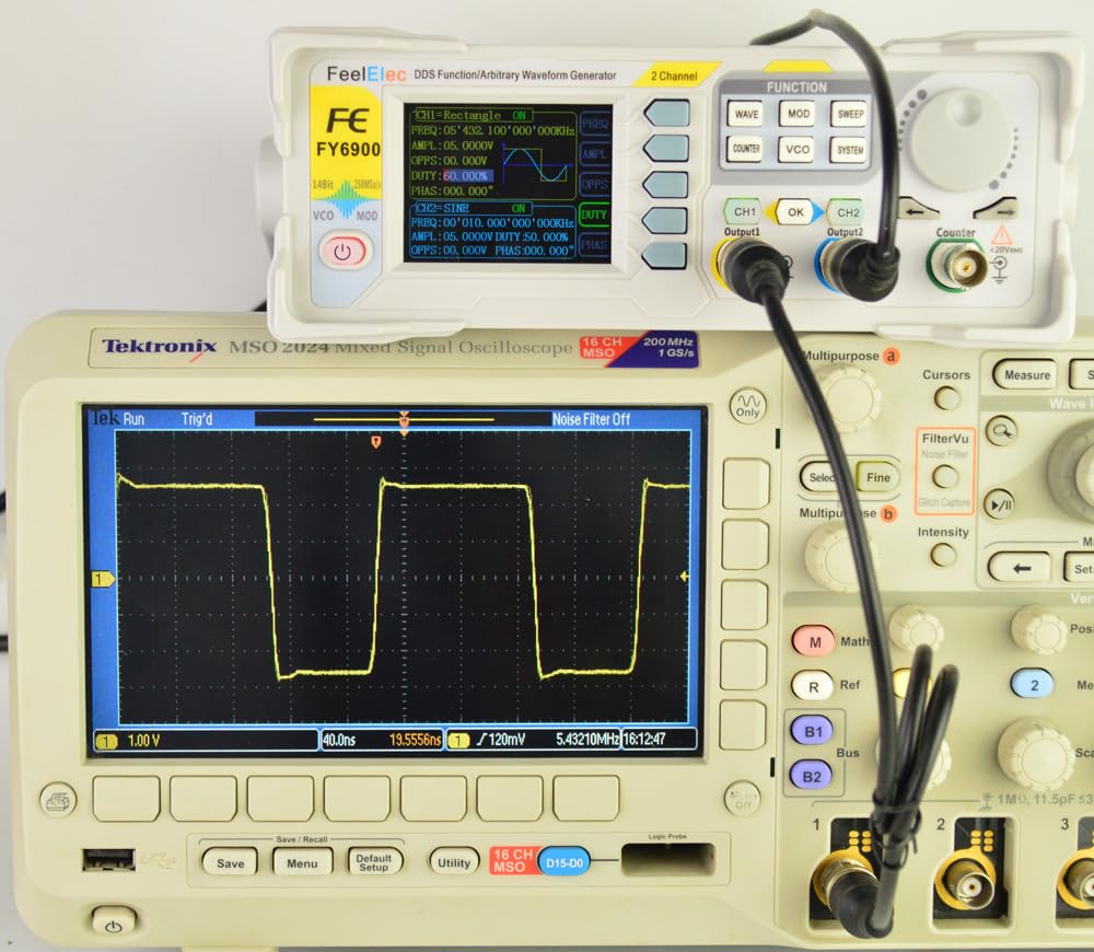
Figure 6.1: Sine Wave Output Example

Figure 6.2: Square Wave Output Example
6.2 Sweep Function
The sweep function allows the output frequency to vary automatically between a start and stop frequency over a set time. Press the 'SWEEP' function key to access sweep settings. Configure the start frequency, stop frequency, and sweep time using the knob and direction keys. Press 'OK' to start the sweep.
6.3 Frequency Counter
The built-in frequency counter can measure external signals. Connect the external signal to the 'COUNTER' input terminal. Press the 'COUNTER' function key to display the frequency measurement. The video below demonstrates various operational aspects of the FY6900, including waveform generation and interface navigation.
Video 6.1: Overview of FeelTech FY6900 DDS Function Signal Generator features and operation.
7. Technical Specifications
| Characteristic | Specification |
|---|---|
| Product Model | FY6900 20M |
| Frequency Range (Sine wave) | 0 ~ 20MHz |
| Frequency Range (Square wave) | 0 ~ 15MHz |
| Frequency Range (Other waves) | 0 ~ 10MHz |
| Minimum Adjustable Width of Pulse Wave | 20ns |
| Minimum Frequency Resolution | 1µHz |
| Waveform Length | 8192 points (8K points) * 14Bits |
| Waveform Sampling Rate | 250MSa/s |
| Vertical Resolution of Waveform | 14 bits |
| Amplitude Range (Peak to Peak) | 1mVpp ~ 24Vpp (frequency ≤ 5MHz) 1mVpp ~ 20Vpp (5MHz < frequency ≤ 10MHz) 1mVpp ~ 10Vpp (10MHz < frequency ≤ 20MHz) 1mVpp ~ 5Vpp (frequency > 20MHz) |
| Amplitude Resolution | 1mV |
| Output Impedance | 50Ω ±10% (typical) |
| Bias Adjustment Range | ±12V (frequency ≤ 20MHz); ±2.5V (frequency > 20MHz) |
| Minimum Bias Resolution | 1mV |
| Phase Adjustment Range | 0 ~ 359.99° |
| Minimum Phase Resolution | 0.01° |
| Display | 2.4-inch TFT color liquid crystal display |
| Interface | 115200 bps |
| Power Supply | AC100V ~ 240V |
| Environment Condition | Temperature: 0 ~ 40°C; Humidity: Less than 80% |
| Product Dimensions | 9.84 x 7.87 x 5.91 inches |
| Item Weight | 2.2 Pounds |
| Date First Available | February 3, 2024 |
| Country of Origin | China |

Figure 7.1: Technical Specifications Overview
8. Maintenance
- Keep the instrument clean and free from dust. Use a soft, dry cloth for cleaning. Do not use abrasive cleaners or solvents.
- Store the device in a cool, dry place away from direct sunlight and extreme temperatures.
- Regularly check cables and connectors for any signs of wear or damage. Replace if necessary.
9. Troubleshooting
- No Power: Ensure the power cord is securely connected and the power master switch on the rear panel is 'ON'. Check the power outlet.
- No Output Signal: Verify that the output channels (CH1/CH2) are enabled. Check cable connections to the test equipment. Ensure parameters like amplitude are set to a visible level.
- Incorrect Frequency/Amplitude: Double-check the parameter settings on the device. Ensure external connections are correct and not introducing interference.
- Display Issues: If the display is blank or distorted, try restarting the device. If the problem persists, contact customer support.
10. Warranty and Support
FeelTech warrants that its products' mainframe and accessories will be free from defects in materials and workmanship within the warranty period. If a product is proven to be defective within the respective period, FeelTech guarantees free replacement or repair of products which are approved defective. This product enjoys a 1-year warranty since its delivery. Damages caused by misuse, vandalism, improper maintenance, or force majeure are not covered by the warranty. Any disassembly or amendment without permission will be deemed to give up warranty rights.
For technical support or warranty claims, please refer to the contact information provided on your warranty card or visit the official FeelTech website. Additional protection plans are available for purchase, including 3-Year and 4-Year options, as well as a comprehensive monthly plan.
Ask a question about this manual
Ask about setup, troubleshooting, compatibility, parts, safety, or missing instructions. Manuals+ will review the question and use this page’s manual context to help answer it.