
1. Introduction
The FeelTech FY6900 series DDS Function Signal Generator is a versatile instrument designed for generating accurate, stable, and low-distortion output signals. It utilizes Direct Digital Synthesis (DDS) technology and features dual-channel output, arbitrary waveform generation, and a frequency counter. This manual provides essential information for safe and effective operation of your FY6900 20M model.
2. Safety Information
Please read and understand all safety instructions before operating the device. Failure to follow these instructions may result in injury or damage to the instrument.
- Power Supply: Use only the specified AC 100-240V power supply. Ensure the power cord is in good condition and properly grounded.
- Environment: Operate the device in a dry, well-ventilated area. Avoid exposure to moisture, dust, direct sunlight, or extreme temperatures.
- Ventilation: Do not block the ventilation openings on the device. Adequate airflow is necessary to prevent overheating.
- Maintenance: Do not attempt to open or repair the device yourself. Refer all servicing to qualified personnel.
- Connections: Ensure all connections are secure before applying power. Avoid touching exposed terminals when the device is operating.
3. Product Overview
The FeelTech FY6900 features a user-friendly interface with a 2.4-inch color display and clearly labeled controls and ports.
Front and Rear Panel Layout

Image 3.1: Front and Rear Panel Layout. This image displays the FeelTech FY6900 unit from both the front and rear. The front panel shows the 2.4-inch TFT color LCD, function shortcut keys (WAVE, MOD, SWEEP, COUNTER, VCO, SYSTEM), a knob button, direction keys, menu softkeys, power key, output terminals (CH1, CH2), and input terminals (Counter). The rear panel illustrates the special function port, 4-channel TTL output, USB communication interface, AC power input, and power master switch.
Key Components:
- 2.4 inch TFT color LCD: Displays waveform parameters and settings.
- Function shortcut keys: Dedicated buttons for WAVE, MOD, SWEEP, COUNTER, VCO, and SYSTEM modes.
- Knob button: Used for adjusting parameter values.
- Direction keys: For navigation and fine-tuning settings.
- Menu softkeys: Context-sensitive buttons for menu options.
- Power key: Front panel power control.
- Output terminals (CH1, CH2): BNC connectors for signal output.
- Input terminals (Counter): BNC connector for frequency counting input.
- Special function port: For advanced functionalities.
- 4 channel TTL output: Provides TTL level signals.
- USB communication interface: For PC connectivity and control.
- AC power input: Connects to the main power supply.
- Power master switch: Main power on/off switch on the rear panel.
4. Setup
Follow these steps to set up your FeelTech FY6900 20M for initial use.
- Unpacking: Carefully remove the FY6900 unit and all accessories from its packaging. Inspect for any signs of damage during transit.
- Power Connection: Connect the provided AC power cable to the AC power input port on the rear panel of the device. Plug the other end of the power cable into a standard AC 100-240V electrical outlet.
- Initial Power On: Locate the Power Master Switch on the rear panel and press it to the 'ON' position. The 2.4-inch color display on the front panel will illuminate, indicating that the device is powering up.
- Front Panel Power: Press the Power key on the front panel to fully activate the device.
- Self-Test: The device will perform a brief self-test. Once complete, the main interface showing dual-channel waveform parameters will appear.
5. Operating Instructions
The FY6900 offers a wide range of functions for signal generation. This section outlines basic operation.
5.1 Basic Waveform Generation
To generate a basic waveform:
- Select Channel: Use the CH1 or CH2 buttons to select the desired output channel.
- Select Waveform Type: Press the WAVE function shortcut key. Use the direction keys or knob to navigate through waveform types (Sine, Square, Triangle, etc.) and press OK to confirm.
- Adjust Parameters: Use the direction keys to highlight parameters such as Frequency, Amplitude, Offset, and Duty Cycle. Rotate the knob button to adjust the value. Press OK to confirm the value.
- Enable Output: Ensure the selected channel's output is enabled (usually indicated on the display).
5.2 Dual-Channel Operation
The FY6900 features fully independent dual-channel output, allowing for synchronous operation with precisely adjustable phase differences.
- Independent Control: Each channel (CH1 and CH2) can be configured with different waveform types, frequencies, amplitudes, and offsets.
- Channel Tracking: Activate the channel tracking function to synchronize parameters between both channels. When tracking is enabled, changes to one channel's parameters can be applied to the other based on user configuration.
- Phase Adjustment: In synchronous mode, the phase difference between CH1 and CH2 can be precisely adjusted.
5.3 Arbitrary Waveform Generation
The device supports up to 98 sets of functions/arbitrary waveforms, including 34 preset waveforms and 64 user-defined waveforms. It has 64 sets of arbitrary wave storage bits, each with a storage depth of 8192*14bits.
5.4 Saving Parameters
To quickly save the currently output parameter information, press and hold the OK button. The next time the instrument is turned on, it can automatically load the saved parameters.
5.5 Example Waveforms

Image 5.1: Sine Wave Output. This image shows the FeelTech FY6900 connected to a Tektronix MSO 2024 oscilloscope, displaying a clean sine wave output from the signal generator.
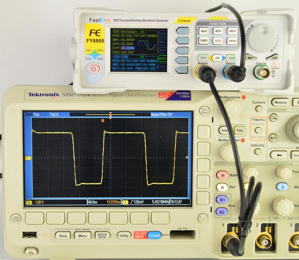
Image 5.2: Square Wave Output. This image shows the FeelTech FY6900 connected to a Tektronix MSO 2024 oscilloscope, displaying a clear square wave output from the signal generator.

Image 5.3: 10MHz Sine Wave Output. This image shows the FeelTech FY6900 connected to a Tektronix MSO 2024 oscilloscope, displaying a sine wave with a frequency of 10MHz.

Image 5.4: 10MHz Sine Wave Output (Amplitude Variation). This image shows the FeelTech FY6900 connected to a Tektronix MSO 2024 oscilloscope, displaying a sine wave at 10MHz, demonstrating amplitude adjustment capabilities.

Image 5.5: 15MHz Sine Wave Output. This image shows the FeelTech FY6900 connected to a Tektronix MSO 2024 oscilloscope, displaying a sine wave with a frequency of 15MHz.
6. Maintenance
Proper maintenance ensures the longevity and optimal performance of your FY6900 20M.
- Cleaning: Keep the device clean and free from dust. Use a soft, dry cloth for cleaning the exterior. Do not use liquid cleaners or solvents.
- Storage: When not in use for extended periods, store the device in a cool, dry place, away from direct sunlight and extreme temperatures.
- Ventilation: Ensure the ventilation openings are not obstructed during operation to prevent overheating.
- Cable Care: Handle power and signal cables carefully. Avoid bending or crimping them sharply.
7. Troubleshooting
This section provides solutions to common issues you might encounter.
- Device Does Not Power On:
- Check if the power cable is securely connected to both the device and the electrical outlet.
- Ensure the Power Master Switch on the rear panel is in the 'ON' position.
- Verify that the front panel Power key has been pressed.
- No Signal Output:
- Confirm that the desired output channel (CH1 or CH2) is enabled on the display.
- Check the amplitude setting; ensure it is not set to 0V.
- Verify that the output cable is correctly connected to the output terminal and the receiving device (e.g., oscilloscope).
- Incorrect Waveform or Parameters:
- Review the frequency, amplitude, offset, and duty cycle settings on the display.
- Ensure the correct waveform type is selected.
- If using arbitrary waveforms, verify the loaded waveform data.
- Display Issues:
- If the display is dim or flickering, try restarting the device.
- Ensure the operating environment is within specified temperature and humidity ranges.
If the problem persists after attempting these solutions, please contact customer support.
8. Specifications
The following table details the technical specifications for the FeelTech FY6900 20M model.

Image 8.1: Product Characteristic Table. This image presents a table outlining the key specifications for various FY6900 models, including frequency ranges for sine, square, and other waves, minimum adjustable pulse width, frequency resolution, waveform length, sampling rate, vertical resolution, amplitude range, amplitude resolution, bias adjustment range, bias resolution, phase adjustment range, phase resolution, display type, interface, power supply, and environmental conditions.
| Characteristic | Specification (FY6900 20M) |
|---|---|
| Frequency range of Sine wave | 0 ~ 20MHz |
| Frequency range of Square wave | 0 ~ 15MHz |
| Frequency range of other waves | 0 ~ 10MHz |
| Minimum adjustable width of pulse wave | 20ns |
| Minimum Frequency Resolution | 1µHz |
| Waveform Length | 8192 points (8K points) * 14Bits |
| Waveform sampling rate | 250MSa/s |
| Vertical Resolution of Waveform | 14 Bits |
| Amplitude range (peak to peak) | 1mVpp ~ 24Vpp (frequency ≤ 5MHz) 1mVpp ~ 20Vpp (5MHz < frequency ≤ 10MHz) 1mVpp ~ 10Vpp (10MHz < frequency ≤ 20MHz) |
| Amplitude resolution | 1mV |
| Bias Adjustment Range | ±12V (frequency ≤ 20MHz) |
| Minimum Bias Resolution | 1mV |
| Phase adjustment range | 0 ~ 359.99° |
| Minimum phase resolution | 0.01° |
| Display | 2.4 inch TFT color liquid crystal display |
| Interface | 115200 bps |
| Power Supply | AC100V ~ 240V |
| Environment condition (temperature) | 0 ~ 40°C |
| Environment condition (humidity) | Less than 80% |
9. Warranty and Support
The FeelTech FY6900 20M DDS Function Signal Generator is covered by a 1-year warranty from the date of purchase. Spare parts are available for a period of 2 years.
For technical support, warranty claims, or service inquiries, please contact your original vendor or FeelTech customer service. Please have your product model number (FY6900 20M) and purchase details ready when contacting support.


